Eric Maynard’s Status Update for 2/29/2020
What did you personally accomplish this week on the project? Give files or photos
that demonstrate your progress. Prove to the reader that you put sufficient effort into
the project over the course of the week (12+ hours).
- Worked on and practiced presentation
- Made a schematic and Eagle PCB layout for the tile’s circuit. See the picture from the design presentation.
- After the presentation, I discovered that our power requirements would subject users to dangerously high currents and unpleasantly high voltage
- Derived several solutions to the power problem
- Solution 1: Increase voltage to reduce current and use a switching voltage regulator on each tile to obtain a usable voltage
- Solution 2: Use batteries on each tile.
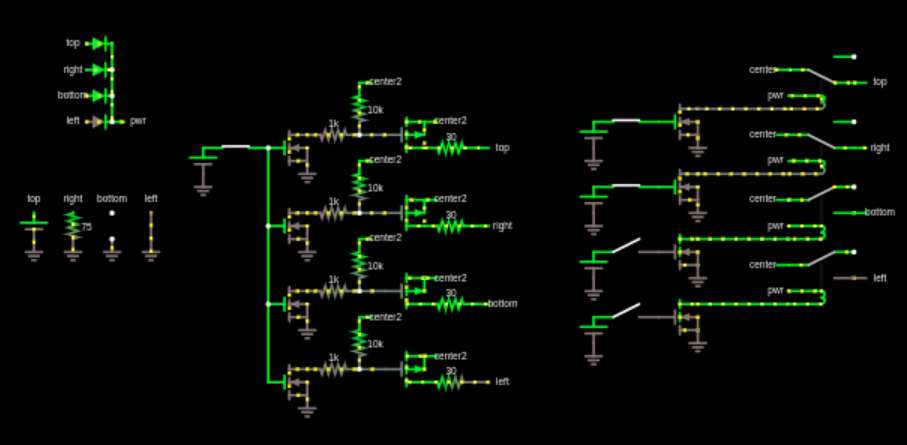
- Solution 3: Use a complicated circuit to limit the current of each exposed port to 100mA. See the following circuit.
- Discussed the problem with professor Mukherjee. He suggested we use on-tile batteries.
- Deciding that we must use batteries, I did a number of tests to get a more accurate image of our power usage. I also wanted to decide how tiles will be turned off and on. I didn’t want there to be a switch on each tile so I checked to see if there is a way to have each tile go into a low power mode after disuse, and then wake up by an external interrupt when the neighboring tile shines a IR light on the tile’s photo-transistor.
- The first challenge was seeing if low power mode is possible. This is a feature that the arduino ide does not surface, but is doable by manually setting some of the micro-controller’s registers. Melodee and I followed a tutorial on this and were able to put the arduino in a low power mode that only drew about 100nA at 3.3v. It normally drew about 3.6mA at 3.3v. See this video. https://photos.app.goo.gl/NJWfbVheeFmuM6yr7
- After getting that to work, we wanted to see if we could configure interrupts to listen for neighboring signals. Our original communication model required the IR lights to be on almost all the time for communication, but if we could use interrupts to capture brief pulses of light, that would be much more energy efficient. Our microcontroller only has 2 external interrupts, but we needed 4 for all the sides. We are using pin change interrupts for the other two sides. This is also not supported in arduino IDE and thus required another tutorial to set up. The result was that we could use those interrupts to wake up from low power mode in about 300 uS and when in active mode, we could capture pulses as brief as 50nS and call the interrupt handler in 20.5uS. The first photo represents the wake-up time, and the second photo represents the interrupt timing.
- Using this information,
- We no longer need to leave the tiles on for any longer than is needed for communication during compilation
- We don’t need an on-switch
- In the “off” state, the micro-controller will draw almost negligible current.
- We can send very brief pulses (limited by the IR circuit) to decrease the energy use of those IR emitters to negligible levels.
- Our testing the week earlier showed that our min current draw is 2.8 volts. This problematic for using batteries because that means that two 1.5 volt cells would be insufficient to power the micro-controller after a short period of use when the voltage drops off. To solve, this, we were going to use either a 9v battery with a switching voltage regulator, or three AAA batteries directly driving the micro-controller. I didn’t want to use the 3 AAA’s because I wanted to limit the number of components and the size of the battery. However, I read that switching voltage regulators draw a non-negligible current when there is no load. Since our tiles will be sleeping most of the time but with the power on, this would slowly drain our batteries.
- I was re-reading the ATMEGA328P’s data sheet when I noticed that the minimum voltage is actually 1.7v, which is much lower than our experimental results. I discovered that I had been setting a fuse bit to enable brown out detection at 2.7 volts which explains why our expermental minimum voltage was so high. Now we can use 2 AAA batteries no problem without worrying about dropping below the minimum voltage. However, if we are switching to a lower voltage range, we need to reduce our micro-controller’s internal clock speed in half, which invalidates the above experimental results. However, because those results were well within range of being useful for our application, I don’t expect the new clock speed to jeopardize anything.
- Talked with Professor Mukherjee and he suggested that we switch to surface mount. This requires re-spec’ing some parts, but should result in a smaller budget and pcb size.


Is your progress on schedule or behind? If you are behind, what actions will be
taken to catch up to the project schedule?
I am behind because of the power problem mentioned above. Now we have a workable solution and schematic and can order prototype parts.
What deliverables do you hope to complete in the next week?
I want to finish refining the final schematic and have the parts ordered Monday for an initial few prototypes.