Team B1 Report for 02/29/2020

Addressing some of the pressing design oriented feedback received:


Some of the feedback we received dealt with how much fidelity the star mount could simulate actual starlight. To address this we plan to discuss the target of each subsystem test. For one, the star simulating mount does not serve the purpose of simulating actual star-light but rather the movement of stars. Since the capture device is out of scope we plan to specify certain restrictions for how much contrast there should be between an object and the “background” (space) in order to allow for accurate “object identification” (tokenization really). This threshold will be tested with generated offsets of real captures taken with a typical entry level capture device (~$700 DSLR cameras [Canon T7i or Nikon D5600]) with 55mm lenses). However, since this is out of scope our stand works with the assumption that these captures meet these metrics [A badly taken capture, for example a long exposure shot of a sodium street lamp, would not meet this].

The rest of the feedback ran along the lines of too little specification in the design presentation as well as some doubts when it comes to competitive analysis. These will all be reflected in the final draft of our design review.


Risks:

There is a risk that Yuyi won’t be able to work much on the circuitry and layout associated with the test setup this week, as CMU’s ECE Open House is scheduled from Tuesday to Thursday of this week. This could push our schedule back because this will leave Kenny to work individually on the circuit design for the laser drivers/motor drivers composing our project’s test setup. Fortunately, the impact of this is unlikely to jeopardize our project. Work on the CV and physical mount is still progressing and the test setup will not be needed until such is completed. Therefore, a contingency plan isn’t really required for this.


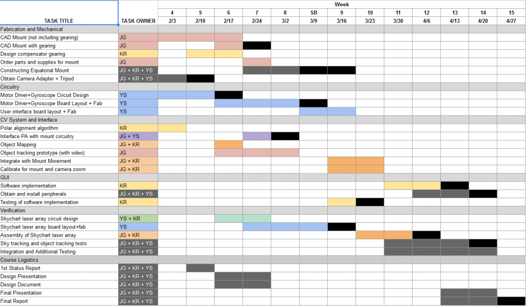
Thus far, we haven’t had a need to make changes to the system’s existing design. However, we intend to push the layout and fabrication of the user interface board of our project to the week of Spring Break. The task will then last until Week 9, when our team will begin integrating the CV with the mount’s motor system. The new Gantt chart is as follows:
Team Status Update for 22 Feb. 2020

Parts that might be falling behind

The selection of an appropriate gyroscope sensor was originally scheduled for this week, but complications with circuit simulation for the motor controller circuit have prevented us from working on it. Fortunately, we are still in compliance with the Gantt chart schedule for this (circuit design isn’t really required for the gyroscope sensor), and we still have a few weeks set out for board layout.

Risk mitigation

There is a risk that our fabrication schedule will fall behind due to some delays and our being unfamiliar with the logistics of doing fab work through capstone. Some solutions to get around queue times/techspark issues would be to go through different venues and simply acquire the material through capstone but the machines through outside organizations like Roboclub.

As far as delays accrued over other portions of the project the only real solution is to revise our schedule after the main set of fabrication is done to more easily catch up on unforeseen complexity.

Additionally, there is a chance that the motor controller PCB will experience catastrophic failure when turned on. We’ve been calculating expected power dissipation/maximum voltages using SPICE simulation for the components to ensure that the components we selected will never exceed their maximum ratings, but simulations don’t truly account for component variations. Furthermore, we’ve only been performing circuit simulations — EM simulation is out of the project scope, so the PCB layout may very well degrade the circuit performance to the point that components are stressed past their ratings.

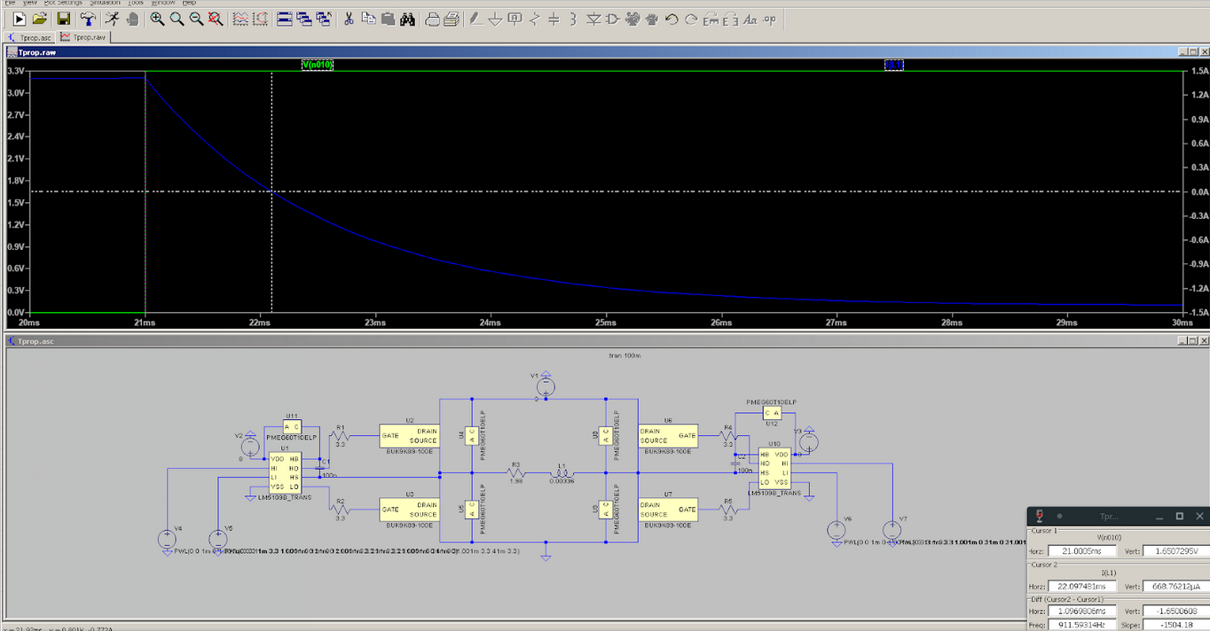
Furthermore, the propagation delays for the motor controller pins could be significantly higher than simulated, producing complications for the programming phase of this project. There isn’t much that can be done about this — data on the digital components of the motor controller circuit is extremely limited and the models we do have appear to be simplistic.

Schedule Adjustments

Right now most of our focus is going towards finalizing fabrication but that was accounted for in the original schedule with several weeks of slack to compensate.

Progress Photos

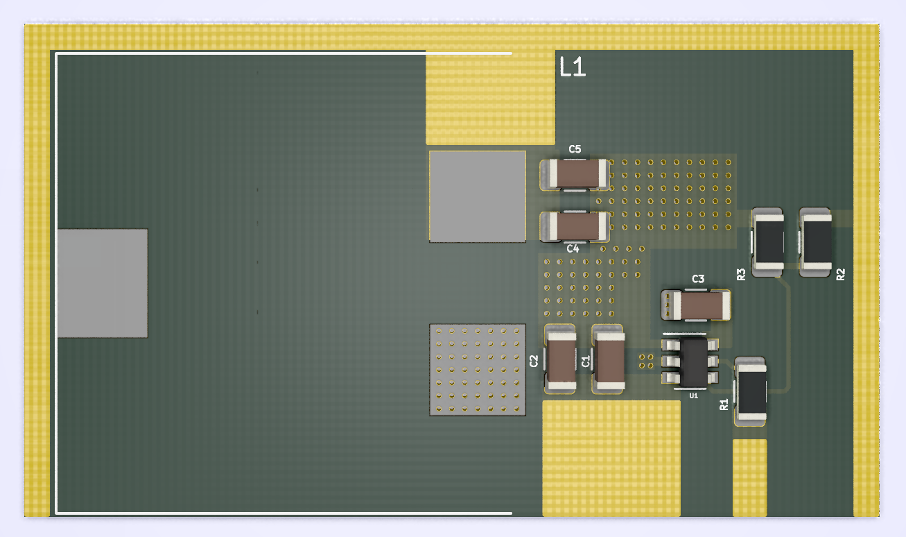
Here’s a 3D render of the 3V SMPS standard cell that was laid out this week for powering our project’s stepper motors. This module can be easily integrated into the final layout for the motor controllers by copy-pasting it in. The 3V output is accessible on 3 sides of the cell, making it more flexible to use during the place and route process.

Team Status Update for 15 Feb. 2020

At this point in the project, we’ve come across risks on both the electronic and mechanical side of the project. If the H-bridge controllers for each of the equatorial mount’s stepper motors are switched improperly, it’s possible for the transistors in the H-bridges to short the motors’ power supplies. The result would be burned transistors, a dead buck-converter IC, and burned out inductors. In the worst case, the PCBs on which the H-bridges are mounted could overheat and blow out. If the traces associated with the H-bridge transistors and gate driver ICs are too long, the parasitic inductance could generate voltage spikes that’ll eventually kill the transistors.

Some of the most critical mechanical challenges are mostly down to the dynamics of the mount. We need to provide accurate enough actuation without going over budget or over scope. Inaccurate fabrication and design could lead to a large discrepancy between our model and our actual mount which leads to higher and unpredictable errors in the final product. A lot of our accuracy is derived from how well we design the gearing at each joint and how well we can predict errors to allow for a lower fabrication cost.

The risks on the electronic component of this project can be managed through careful layout practices and the usage of circuitry to prevent the appearance of inappropriate control signals at the H-bridge inputs (such as an inverter between inputs that are known to be complementary).

The risks of the mechanical component of the project can be managed through careful prototyping and simulation. Contingency plans have also been discussed for the more complex and error prone portions of the fabrication.

Fortunately, we have not seen fit to make changes to the existing design of the system this week. None of the design challenges we tackled in order to meet the design specifications we set earlier were impossible or infeasible.

We’re planning to use a week of slack time (that was already allocated in our initial Gantt chart) to finish up the circuit design for the equatorial mount’s motor drivers and gyroscope sensor. Otherwise, there have been no changes to our plans.

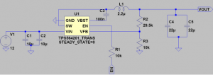
At this point, we’ve specified parts for the mount motors’ power supplies, and have selected components for the motor driver circuits:


LtSpice simulation has also been used to characterize the motor driver designs for propagation delay in preparation for programming the Raspberry Pi:

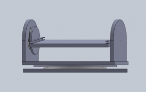
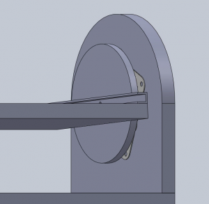
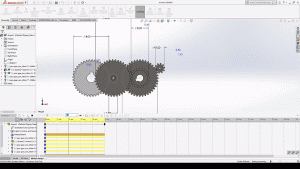
The general structure of our mount has been laid out in SolidWorks: