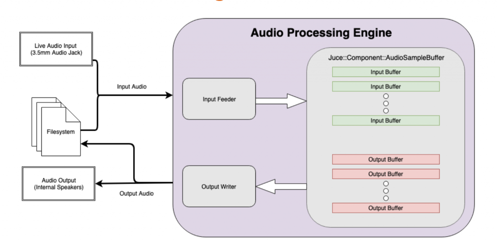
The first action item for this week was to work on the design document, which we submitted Monday afternoon. This was really a team effort–the three of us got together for several hours on Sunday to work on the document as well as go over the feedback from our design presentation. I think that this was a very helpful step, which allowed us to get on the same page about the vision we had for the project and what steps we were going to take to get there.
One thing in particular that we had to dive deeply into was our testing procedure, as there were still several unanswered questions on that front, which were pointed out in the design review. The main question we face is how to determine if our pedal simulator is truly accurate. After some careful thought, we devised a testing plan based on a metric called normalized cross correlation, which can be used to measure the similarity between two signals. Our original hope was that we could simply use a physical guitar pedal as a reference model, and compute the normalized cross correlation between the signal coming out of that pedal and our simulated pedal. This left unanswered several questions, such as how do we ensure that the input signal is consistent for the simulated pedal and the reference pedal? How do we account for phase differences that can occur due to measurement timing? We ultimately revised our naive testing procedure to use an audio splitter to derive the reference and test signal from the same source. To account for phase differences, we will take the normalized cross correlation between our reference and test signals at a variety of phase offsets, treating the maximum correlation as the “score” in our testing procedure. I think that it was particularly valuable to work out how the testing will work for me, since I am primarily working on the pedal circuit simulator.
This brings me to the other work I got done this week. At this point, the simulator seems to be able to handle all types of resistor configurations, as well as some nonlinear components such as inductors and capacitors. I think that some further unit testing will be required before I am ready to declare this phase of the project a success, and I will be working on this near the end of spring break. However, I am very satisfied with my progress this week as it relates to the capabilities of the circuit simulator.
As far as next steps and my schedule moving forward, testing is going to be a really big deal in the next week or so. I’m hoping to build up a suite of circuits that have well known behavior, such as RLC filters, so I can perform basic sanity checks to tell whether my simulator is producing sensible results. I also hope to add models for other nonlinear components such as diodes and MOSFET transistors, which we hope to be able to support in our final product. However, testing the existing infrastructure is going to be my priority, rather than adding support for new component types, until I am satisfied with the simulation accuracy for the components already implemented.
Since circuit simulation is uncharted territory for me, I’ve been working in Python for now so that I can get comfortable with the algorithms and techniques in a language that allows me to iterate rapidly, make changes on the fly, and reason about the code without worrying about low level details. However, I also know that eventually this simulator needs to be fast. At some point in the next two weeks, I would like to start porting over some of my successful experiments to C++, which should result in better and more predictable performance.
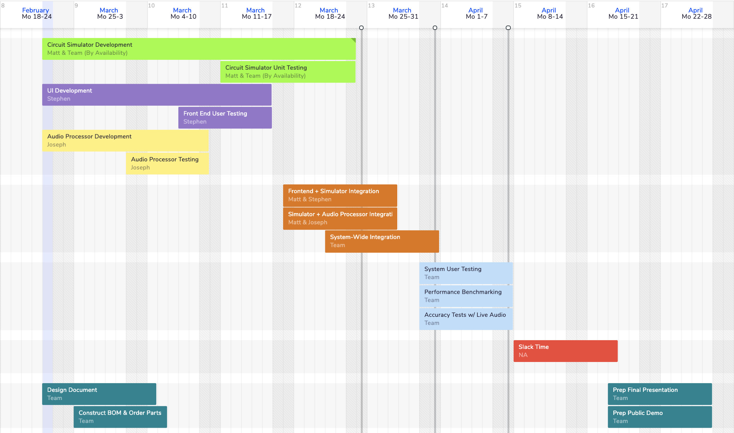
Overall, I’d say I’m pretty on schedule based on what we submitted as out team schedule in the design document. I also have a lot of free time over spring break once I get back to Pittsburgh on Thursday, so I should have an opportunity to keep pushing forward this week.


