This week, I’ve been splitting my time between working on the design review and working on a basic circuit simulator. At first, I kind of felt as though the design review was somewhat distracting me from getting to work on the actual implementation of the project, but over the course of this week, I have come to the conclusion that the design review was actually really useful because it forced me to consider aspects of my design that I had previously glossed over and formulate ideas in writing that had previously only existed as fuzzy thoughts in the back of my mind.
Design Review
With that in mind, the first thing I did this week was lock down a formal design for the circuit simulator. This design is shown in the block diagram below.
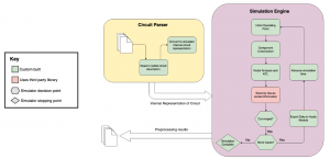
Ultimately, the circuit simulator is going to be broken down into two main parts. The first is a circuit parser, which translates a netlist description of a user’s circuit that was passed to the simulator from the front end into a custom, internal representation. This representation is really just a vector of components and some metadata to keep track of which nodes everything is connected to. From there, this internal circuit representation can be passed along to the simulation engine, which is responsible for doing most of the heavy-lifting. The algorithm we settled on involves several steps:
- Construct linear approximations for all non-linear components
- Perform KCL and Nodal Analysis to derive system of linear equations
- Initialize solution matrix to initial “guess” state
- Use Gauss Jordan Elimination to solve system of linear equations
- Continue to iterate using Newton’s method until solution has converged to within acceptable error rate.
We also plan to pre-simulate complex circuits against a variety of states and sample inputs, with the hope that this can enable us to do faster processing of live signals at the cost of some additional up-front processing time.
Simulator Implementation
In the leftover time after preparing for the design review, I’ve also had a chance to work a bit on the implementation of the actual simulator. In my last status update, I mentioned that it was my goal to be able to simulate a basic RC low-pass filter this week. Unfortunately, I thing that goal was overly optimistic for two reasons. First was that I underestimated the time that I would have to spend preparing for the design review presentation, which obviously cuts into my implementation time. Second, simulating an RC filter, though it is a seemingly simple circuit, is fairly complicated as far as the simulator software is concerned. This is because capacitors are nonlinear components, which depend on energy stored on past iterations of the simulator. This makes the simulation much more complex, and I’ve run into some bugs in the implementation that I have not yet had the time to resolve. I’ve also decided that I am going to write a proof-of-concept version of the simulator in Python first, then port it over to C++ once the kinks are worked out in the simulation algorithm. This is because Python allows me to debug, iterate, and try new things much faster. Since we’re not yet worried about speed, I felt as though this could be a good approach to take for a week or two until I’m comfortable with the algorithms behind the simulator.
However, I was able to complete some things this week. For example, the netlist parser is nearly entirely completed, and it supports components such as resistors, capacitors, diodes, and voltage sources. Probably the only remaining component that we would need to add would be transistors, which are a bit unique because they are not two-ported components. An example of the netlist representation of a basic RC filter is shown below.
RESISTOR r1 0 1 100k                    # 100 kohm resistor
CAPACITOR c1 1 2 100u                   # 100 microfarad cap.
VOLTAGE_IN vin 0 2 voltage_in.txt       # voltage input
VOLTAGE_OUT vout 1 2 voltage_out.txt    # voltage output
GROUND 2
The code used to parse files like this can be found in this Github repository. This repository does not yet contain the code for the simulation engine.
Outlook
I would say that I definitely came up short of the goals I set for myself last week. However, I think that I can still be on track given that my goals last week were a bit ambitious. In fact, once the simulator is capable of handling an RC filter, adding diodes and inductors is really just an extension of the same principles. The next major hurdle from there will probably be adding transistors, then making sure this code runs fast enough to meet our goals. Next week, I truly do hope to have an RC filter running against recorded audio, and perhaps a bit of work done on inductors and diodes as well.