Status Update – Matt (04/06/19)

This week, I got a lot done in advance of the mid-semester demo. The first thing I accomplished was getting nearly all of the circuit simulator rewritten in C++, which turned out to be tens of times faster than the Python version we’ve been working with so far. I’ve noticed speedups of 50-70x over the Python version when running the C++ version compiled with -O3 on the same inputs depending on the circuit. For simple circuit configurations, we’ve been able to process inputs sampled at 44 KHz lasting tens of seconds in under a second of simulation time. I expect that this speed will tail off a bit once we start to deal with increasingly complex circuits, but this was a hopeful sign in terms of our aspirations to eventually operate on live audio signals. The full source code for the simulator can be found in the backend directory of our repository.

We also worked quite a bit on integration this week. For me, this involved multiple steps. First, I worked with Joseph to integrate the circuit simulator with the audio processor. To accomplish this, we decided to create an interface called AudioManager, which provides the circuit simulator with a consistent API to read in signals/voltages regardless of where they may come from. This allows us to use a variety of audio file types or even a live instrument to provide the circuit simulator with an input signal. Regardless of the input source, the AudioManager handles all of the source specific details so that the simulator does not become polluted with logic to interact with audio hardware or parse wav files. I think this integration worked out quite nicely, especially since we can now support new audio sources without having to modify the simulator at all.

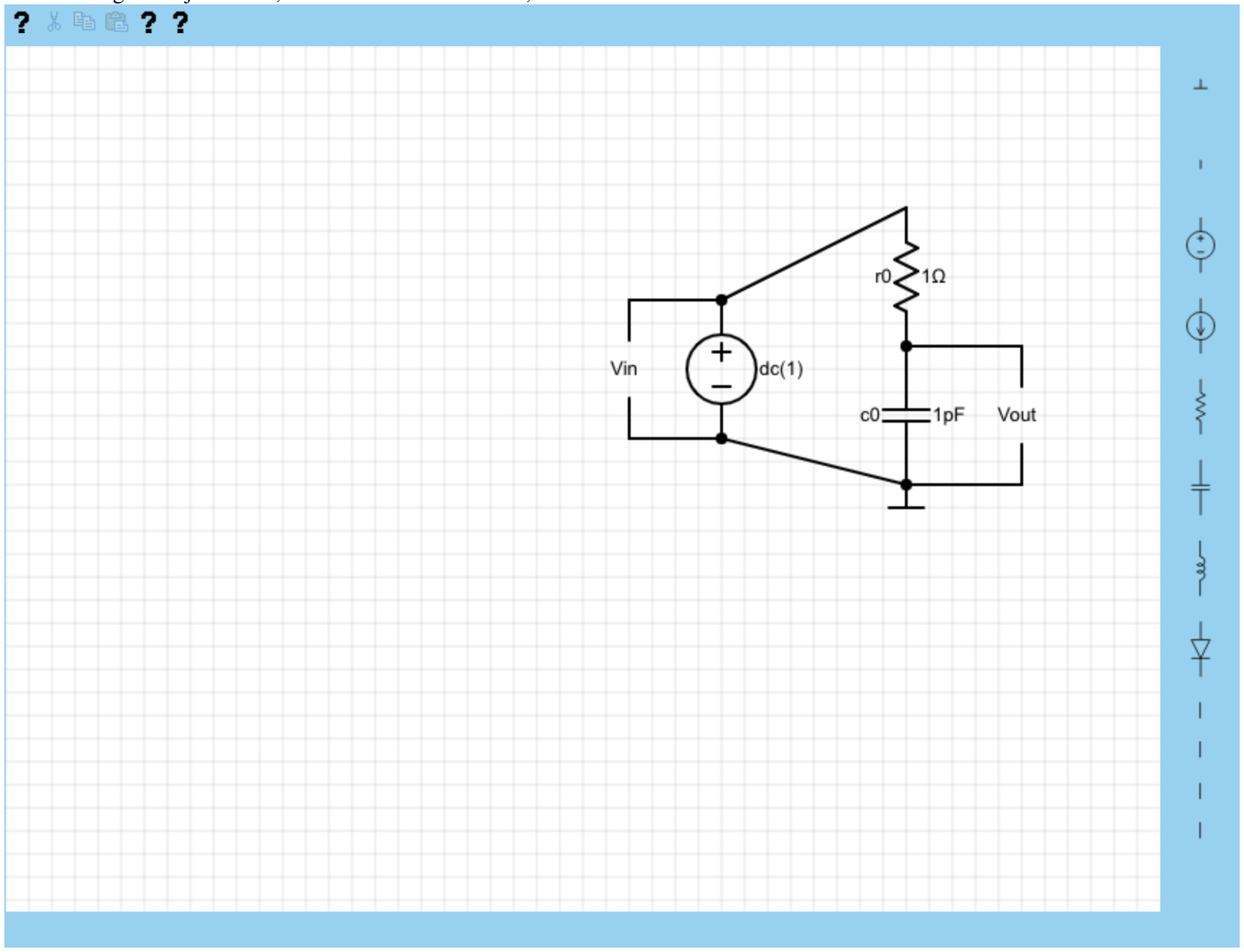
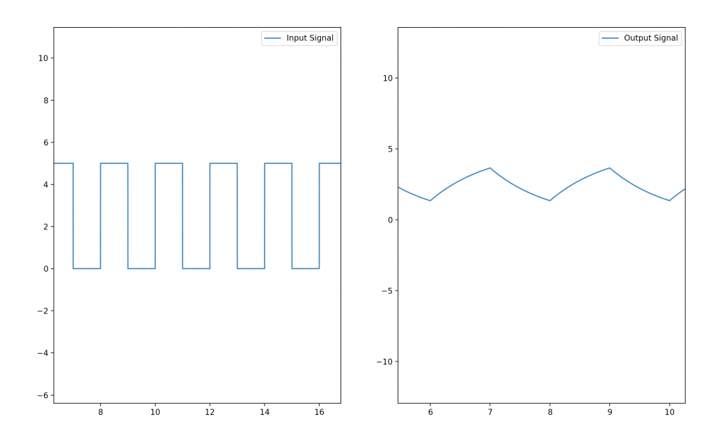
I also worked with Stephen to integrate the circuit simulator with the frontend. The way this works is by having the frontend use the fork/exec system calls (via a Javascript library) to run an instance of the circuit simulator. All communication necessary happens via a command line interface that I implemented in the circuit simulator. Stephen’s frontend simply provides the simulator with the appropriate arguments, such as the input signal source used to instantiate the AudioManager, the netlist file containing the circuit to be simulated, and the user’s chosen name for the output audio file. Additionally, there is an optional –plot argument, which causes the circuit simulator to pipe simulation results into a Python script for plotting using matplotlib when specified. This is a nice option to use for debugging or if the user wants to see a graphical representation of how their circuit behaves.

I’m currently working on implementing diodes, which will enable us to expand into clipping effects. I am hoping to have this done by Wednesday of this week, and then I can move into implementing transistors, which is the last type of component we hope to support. Once all component types are integrated, I hope to begin conducting more extensive tests on the accuracy of the simulator. I am certain that more complicated circuits will reveal some bugs and I want to have ample time to fix them.

Status Update – Team (03/30/19)

This week, we did a couple things as a team:

We finalized our goals for the upcoming demo.

We spent time going over our testing plan. This involved seeing how the hardware (guitar + pedal) interacts with our laptops. After meeting to discuss our test plan, we realized we needed more materials, so we placed a second parts order for a new USB audio interface. We plan to meet on Sunday to work on developing the final details of our testing protocol.

We also worked on integrating each of our parts together. This was done by defining the communication method between parts, as well as defining what we expect the incoming data / information to look like. For example, Matt formally defined the netlist format for me to implement in the front end. This is described in detail in our github. We were ultimately able to get some integration done: the audio processor was able to send recorded audio through the circuit simulator, and the simulator could export the results back to the audio processor for playback. The frontend is now capable of producing netlists in the same format as the circuit simulator expects.

Next week, we plan to continue on integration, as well as development of the circuit simulator and frontend.

Status Report – Joseph (03/30/2019)

This week, I worked together with Matt to make it possible to send either microphone input or file input to the circuit simulator, then have it play out in the speakers. This was written for the preliminary simulator written in Python, so we’ll have to make some adjustments when the simulator is ported to C++, but the core part of the input/output processing is done.

Though the initial plan was to help out with the circuit simulator afterwards, we decided that it would be more efficient for me to start working on the testing platform instead. So, I’ve made a tool to visualize input and output audio samples in both the time and frequency domains, and am working on adding the cross correlation test to it.

I want to continue working on the testing framework and have the core of it done by the midpoint demo so we can showcase our work. Afterwards, I can add features that make it easier to test like automatically running our results against SPICE’s.

We also ordered and received the new audio interface, which supports two inputs. Using that, I’ll also be working on getting both the clean sounds and distorted sounds from the same guitar at once.

Status Update – Stephen (03/30/19)

This week, I primarily worked towards getting our front end ready for our upcoming demo.

I made a lot of progress with the front end! This is how it currently looks:

On the top bar, we have some icons for different actions. The first button opens up a help screen (currently not implemented). The fourth and fifth buttons (also question marks, a WIP) are import and export, respectively. These buttons work as they sound: import allows you to import a circuit from file, while export allows you to export a circuit currently existing on the canvas to file. The export functionality is the main way the front end interacts with the circuit simulator backend (the backend reads the file as a netlist to understand the circuit).

On the right, we have the different components you can place into the canvas. They are in order: Ground, NA (nothing), Voltage Source, Current Source, Resistor, Capacitor, Inductor, Diode, Voltage In, and Voltage Out.

All of the components are mostly implemented as of now, except I have only implemented the import and export feature for Ground, Voltage Source, Resistor, Capacitor, Voltage In and Voltage Out. This is because these are the components we needed for our demo. However, it should be relatively easy to implement import and export for the other components quickly.

I also implemented a naming system for each component. This can help the user distinguish between components of the same type in a circuit. In the picture above, the component names are r0 and c0 for the resistor and capacitor, respectively. The naming system I implemented increments a counter such that each successive resistor will have a different name with an incremented number. This also takes into account when users delete and copy / paste components onto the canvas.

In addition to this, I also worked on our Ethics assignment this week. This involved a class discussion, as well as spending time writing a list of changes for my first ethics assignment.

I think I got a lot of progress done this week! I hope to continue that into next week. Next week, I hope to have import and export working for each component, and also the signal visualizer half of our front end working.


Status Report – Matt (03/30/2019)

This week, I’ve continued to work on the circuit simulator. I spent some time working with Joseph to get it partially integrated with the audio processor ahead of the mid-semester demo.  We succeeded in getting a recorded audio file passed through the simulator and playing back the result, which was a big milestone for us.

I’ve also started implementing the simulator in C++, as I’ve been working in Python lately to enable a fast development pace and faster debugging. Ultimately, working in C++ enables easier communication with the audio processor and should make the simulator quite a bit faster as the circuits start to get more complicated. I hope to get much of this work done in the next couple days and it should be finished before our demo on Wednesday.

We also plan to meet tomorrow to continue to refine the product we hope to produce for our demo. In particular, we hope to be able to finalize the details of our testing procedure that should enable us to gather quantitative error measurements of our simulator now that we have the USB audio interface we need. Going forward, my primary goal will be to get the simulator ported over to C++ as quickly as possible (probably a couple days work), implement transistors and diodes in the simulator, and finalize the testing procedure.

Status Update – Joseph (03/23/19)

This week, I worked on a few things. Our parts arrived for the pedal we are testing against, so I spent a few hours assembling it. It took longer than I initially thought, since the circuit is fairly simple, but having to solder in a small confined space with a rusty soldering iron proved more difficult than I initially thought (I had to get another soldering iron eventually). Once the pedal was built, I tested it with a guitar to make sure it was working as intended.

I also spent considerable amount of time trying to figure out how our audio processor built on JUCE was to be integrated with the rest of our application. While JUCE made it really easy to get started and was well documented, it was difficult to get out of the environment it sets up. I spent many hours trying to get the build to work with a Makefile rather than on XCode. Though JUCE also gives users the ability to generate a CMake, it was only compatible on linux systems and not on OS X, our main target platform. I looked into an open source code named FRUT that claimed to do what I wanted, but that didn’t compile successfully either.

Considering the fact that our Audio processor is much simpler than we initially imagined it to be, we decided that the JUCE library was a lot more heavyweight than it needed to be. So, after a bit of research, I decided to switch over our platform to use Portaudio for audio I/O and Libsndfile to read audio files. These solutions are way more lightweight, requiring me to only put in two linker flags to compile. The only downside is that the documentation is way more limited — the C++ wrapper for Libsndfile didn’t have any written documentation at all, so I just had to read source code and header files to figure out what they did.

Most of the functionality of the audio processor is done now, so next week, I want to focus on our testing pipeline. I need to figure out how to split the audio signal from the guitar/preamp, and record it on two computers. One computer will have the pedal we built connected before receiving the signal, giving us a way to get both the clean audio signal and the distorted signal. With this, we should be able to run the clean signal through the circuit simulator and compare it against the real circuit signal.

Status Update – Team (03/23/19)

These past two weeks, we’ve made a couple key pushes forward as a team.

First, we finally got our parts order submitted! Because Sullivan had a lot of resources in his audio lab, we were able to limit our purchases even more than we planned. The parts came in earlier this week, and we spent some time assembling the simple pedal we purchased.

We also started working on hashing out our integration plan. We are focusing on the integration aspect because the midsemester demo is coming up in a week and a half. By then, we want to be able to show the full flow of our project with a simple test circuit and audio sample. We’ve been focusing on individual modules up until now, so this integration plan was a change of pace.

Along that note, we made a change to our audio processing module to help with the integration plan. We realized that the JUCE library was very heavy for what we needed, so we decided as a team to switch to a different library. Hopefully we’ll see the wiseness of our choice next week.

We also spent some time discussing our requirements and vision for the midsemester demo. We wanted to all agree on what we wanted to have ready for the demo so that no one was stressed or surprised. We agreed that we wanted a demo of simulating a real time sound on a low pass filter ready.

Next week, we plan on working together to fully integrate our project. After that, we can start building out a testing suite. Lots of exciting things are now going to happen!

Status Update – Stephen (03/23/19)

It’s been two weeks since the last status report! The first week was spring break for us, so it felt good to get back into the groove of things this past week.

The first thing I worked on was the Ethics assignment. For it, I read the case study found at https://www.scu.edu/ethics/focus-areas/more/engineering-ethics/engineering-ethics-cases/may-the-truth-be-with-you/. It describes a situation where an employee realizes that her company sold defective goods to a customer. She has to decide between telling the customer the truth, or helping her company’s bottom line by charging for the repairs. It was cool to read because I thought that the scenario was very realistic – I could definitely see this happening in the industry today.

Next, I put some more time into working on the front end for the circuit simulator. I found a very competent javascript circuit simulator written by MIT here at https://github.com/zupolgec/circuit-simulator. To give direction to my efforts, I used this as a guide on how to implement our simulator.

Our simulator is built with a class based programming style. We currently have the following classes: the Schematic class representing the whole system, the Component class representing individual circuit components, the ConnectionPoint class representing connections between circuit components, and the Wire class representing wires. There are also classes that inherit from the Component class: Resistor class, Inductor class, Capacitor class, etc.

The Component class has methods like rotate, move, add and remove. These do as expected. The subclasses of Component (like Resistor and Inductor) have their own personal draw and toString methods.

The Wire class represents the wires connecting instances of the Component class. It has a method bisect which checks whether or not any component currently bisects a wire. If there are, then the bisected wire is deleted and two wires are created that represent both halves of the bisected wire.

The Schematic class holds all the methods that tie the whole visualizer together. It’s in charge of holding and drawing all of the circuit components added by the user. It’s also in charge of handing when the user wants to export circuits to and import from file  (though, these features aren’t done yet 🙁 ).

Overall, I think I got a nice bit of progress in this past two weeks. Obviously, there is always more to be done, but I definitely feel like I’m on track.

This upcoming week, I want to finish working on the export and import features. This is really important to finish because our midpoint demo is coming up! Next week is really going to be all about integration.

Status Update – Matt (03/23/2019)

This week I spent a lot of time refining the circuit simulator. I also worked on developing some tools by which the simulator can be easily tested against a variety of input waveforms. At this point, I am very confident that components such as resistors, capacitors, and inductors work correctly. This is more than enough to build basic filters. In order to implement some of the guitar pedal effects we want, we’ll also need to test diodes and transistors. This could prove to be a bit more challenging, as the IV curve for a transistor is not really the same from device to device like it is with capacitors, inductors, and resistors. Ultimately, implementing these components will probably require us to read some datasheets for the exact transistors/diodes that make up the pedal we are trying to simulate.

I also worked on a test suite of small circuits and waveforms that can be used for testing. I wrote a small script that generate waveforms (either sinusoids, square waves, or high frequency noise) and export them in the format that the simulator expects as input. I also manually created a few new circuit netlists for testing. Now that we have our test suite set up, we are able to look at some more complicated waveforms. For example, here is high frequency noise being passed through an RLC low pass filter. It is clear that the filter smoothes out some of the high frequency components of the original signal.

This also allows us to test the models for individual components using extremely simple circuits. For example, we can verify that our capacitor model behaves in a reasonable manner by looking at the following waveform, showing the response of an RC filter to a square wave:

This allows us to do a basic sanity check of our component models–it is clear from this waveform that the capacitor charges and discharges as expected.

This allows us to have higher confidence in the accuracy of our simulations, but ultimately it is still a qualitative approach to testing. Much of our efforts over the next week will be spent on implementing our full test bench to enable us to really quantify our error/accuracy. We also plan to meet on Sunday (3/24) to integrate all three of our components ahead of the in-lab demo which is right around the corner. This will probably take a fair amount of my available time next week, and we also lose one working day in lab for the ethics discussion, but I hope to also have some time to test the diode model in the coming week. I ultimately think that I am fairly on-track, though I do think I should speed up my development pace a bit in order to account for the fact that bugs are likely to arise as we progress, and I want to have time to deal with them without killing our schedule.

Status Update – Team (03/09/2019)

This week, we spent some of our time together working out the final details of our design ahead of the design document that was due on Monday. One of the big things this involved was hashing out our test procedure in greater detail than we had ever done before. Ultimately, we decided on a protocol (which we discussed in lab this week) that involved using an audio splitter to derive our reference and test signal from the same source at the same time. We could then feed one of these signals through a real guitar pedal, and another through our simulated version, before using normalized cross correlation as a metric to measure the similarity between the two.

We also placed an order for parts just before break. Professor Sullivan is kindly allowing us to use his audio lab, which eliminates the need for many of the components we had planned to order. However, we did request a few parts such as a reference guitar pedal, and the splitter cable we need. We chose a DIY pedal that had simple circuitry on the inside, and we carefully chose one that consisted entirely of components we plan to support in our own simulator.

Much of the other work we have been doing lately has been on our own individual parts. Matt has been working on the circuit simulator, Stephen on the UI, and Joseph on the audio processing. We ultimately hope to spend about another week or two on development and unit testing before we begin integration. Some parts of the project have made good strides this week, but there’s still a lot left to do, which is why we all intend to dedicate some time over spring break to getting our components up and running.