Updates

Mike’s Weekly Update, Mar 10 – Mar 23

Worked on figuring out programming the LED matrix and figuring out how to integrate the matrix onto the jacket.

In order to reduce memory usage on the Arduino, there had to be some clever tricks used to minimize the representation of the matrix images.

// bit representation of signal image on matrix
left_turn[] = { 
0B1000000000000001, 
0B0100000000000010,
0B0010000000000100,
0B0001000000001000,
...
}

void show_matrix (uint16_t M[], int r, int g, int b) {
  int curr_led = 0;

  for (int col = 0; col < WIDTH; col++) {
    uint16_t curr_bitvec = M[col];
    uint16_t mask = 0B0000000000000001;

    for (int row = 0; row < HEIGHT; row++) {
      if (curr_bitvec & mask == 1) {
        leds[curr_led] = CRGB(r, g, b);
      } else {
        leds[curr_led] = CRGB(0, 0, 0);
    }

    curr_led++;
    curr_bitvec = curr_bitvec >> 1;
  }

  // Skip LEDs that loop around at the corners
  for (int i = 0; i < NUM_LEDS_SKIP; i++) {
    if (curr_led < 300)
      leds[curr_led] = CRGB(0, 0, 0);
    curr_led++;
  }
}

By using a bit-vector instead of a naive integer matrix, we save (SIZE_INT – 1) * 256 = 992 bytes per 16×16 image.

An image from testing the matrix code:
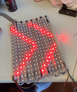
Many possible mounts for the matrix onto the jacket, but the biggest concern is flexibility while maintaining integrity of the matrix to stay on the back. The most likely approach is to glue the matrix onto a clothe, which is then screwed or sewn onto the jacket. Heat shrink wrap and hot glue will serve as waterproofing for holes that have to be put into the jacket.

There is also a preliminary communication protocol that has been developed for the Arduino, which will be utilized when the Raspberry talks to the Arduino via Bluetooth.

Ben’s Weekly Update, Mar 10 – Mar 23


Saturday (16th)

Worked on the LKM, but after working a while decided to switch to pigpio instead of using an LKM because measuring pulse width requires two interrupt handlers, one for rising and one for falling edge, or requires checking the pin level within the interrupt handler, which apparently takes a uncertain amount of time. Using pigpio instead polls the GPIOs at a set frequency, while this still isn’t the most accurate, at least the error will be predictable and there is no need to mess with the kernel.

Sunday/Monday (17th/18th)

Worked further on the proximity sensors (ultrasound). Managed to get two working at the same time using my program interfacing with pigpio. Wrote the library to support six, which is the number we need. Am mildly concerned about the performance of the rest of the software running on the pi given the pigpio’s need for polling, but so far it seems like it is okay. Would consider the proximity sensors essentially ready for testing.

Tuesday/Wednesday (19th/20th)

Worked on the bluetooth connectivity between the Pi and the Arduino. Figured out how to configure the HC05 bluetooth module for the Arduino to use. Tested out the C libraries for the Pi’s Bluetooth connectivity.

A1 CycleSafe Weekly Update, Mar 3 – Mar 9

Updates

  • Almost lost our jacket after leaving it in 1303, but fortunately found it later. We will be more careful with it in the future.
  • Design review report completed. The report allowed us to put specifications and find data on a lot of things that we were mostly giving ballpark values for. Finding such data allowed us to have more confidence in the situations in which CycleSafe will be useful, and to make our requirements more precise in some areas, such as reaction time, braking distance, power requirements, and visibility.
  • Looking forward, spring break and the week after will probably just be grinding through the works of putting a prototype together.

Ben’s Weekly Update, Mar 3 – Mar 9

Sunday

  • Worked on design review report

Monday

  • Worked on the design review report.
  • Further refined the testing procedures. Interestingly one of the things brought up during the design review presentation will help a lot with testing. The fact that the speedometer will be connected to the Pi via an Arduino will enable easier testing because bicycle speed can be simulated simply by programming the Arduino to report a certain speed.
  • Noticed from looking at vehicle system testing procedures that generally very few tests are carried out. The primary metric is the time and distance at which the warnings go off, and whether warnings persist all the way through the danger. So the test were designed similarly to have the main metric for a successful test be the time-to-impact when the warning goes off and the persistence of the warning.

Wednesday

  • Started working on the Bluetooth interfaces between the Pi and the rest of the system. Worked on hashing out the communication needs and protocol between the Pi and the Arduino on the jacket.
  • Realised the communication needs between the Pi and the jacket are not very significant, and some communication requires guaranteed transmission while some communication just needs to get to the jacket quickly and can just be constantly transmitting. Will be interesting to see how the Bluetooth can be utilized for this.

Saturday

  • Starting working on the LKM for the Pi. Need to get interrupts going for the ultrasonic sensors.

Michael’s Weekly Update, Mar 3 – Mar 9

Accomplishments

  • Finished design review report
  • Acquired a jacket for the wearable component
  • Designed waterproofing for LED strips (heat shrink)
  • Designed a sew-on component for the LED strips instead of directly gluing it on the jacket
  • Preliminary sketches for possible 3D-printed waterproofing shells on the bike

Future

  • Prototype a few waterproofing shells
  • Build the jacket

Status Report #3 Sid

Sid Lathar, A1 | Progress Report #3

Accomplishment:

Following previous week’s report the method was implemented into the Hello world app. The app can now use Google Maps API to get current coordinates of the phone and get the nearest intersection to it.

Changes to schedule:

The progress is on schedule.

Upcoming work:

By next week I plan to implement the following features into the app:
– Basic UI to toggle intersection search (right now it’s ongoing as long as the app is running)
– Plan the layout for the app
– Research on communicating with the Pi

Michael’s Weekly Update, Feb 24-Mar 2

Accomplishments this week:

  • Designed signal light patterns. Since at full capacity, the LED strip can consume 12 – 15 A at 5V, we need to be careful about turning on all of the light s at the same time. Therefore, I designed some light patterns that try to be conservative on the number of LEDs used.

Above: brake light is the entire panel, but at low power
Below: Turn signals, we are not using all the lights.

  • Listened to other presentations, and received feedback from Prof. Ken about what steps to take in the future, which include batteries and weight specs.
  • Received LED matrices, wrote code to interface with the matrix.
  • Drawing diagrams and helping write the design review paper.

Concerns:

  • The LED matrix code is not hard to write in terms of turning 2D data[][] into 1D serial data to be interpreted by the Arduino, but the problem is that if we want to store signals that are very specific, a single 16×16 bit-vector to describe a signal is very expensive, if we have around 100 such signals. This is made worse, since the Arduino Nano also has a very limited memory. One possible solution we may have to consider, is to offload the signal memory to the Pi, and then have the Pi send over communication the signal that the Nano should be displaying. This can be cached, for better performance, so we don’t have to fetch 256 bits every time we want to display a signal.
  • We are bit worried about how much battery power we need. We are currently thinking about one on the bike and one on the jacket, the Pi and the LED matrix are the two biggest energy suckers.

A1 CycleSafe Weekly Update, Feb 24-Mar 2

We had presentations this week, and were able to see many aspects of how even projects that were well underway and seemingly on a good track still could use some design reflections and feedback.

For our team specifically, we mostly missed out on specifications for our battery life and weight. This is a very important aspect of our product, as the first two things a consumer are probably going to consider in our product are:

  • Will the battery life last long enough?
  • Will the device be bulky and unwieldy to put on the bike/my body.

Our plan is to conduct some sort of competitive analysis on other similar situations, and the other is to conduct a small user test to see how people respond to weight and battery life. We met with Prof. Ken Mai as well to talk about other ways to find solutions for our problem.

We also received a concern about how we plan to measure the brightness of our LEDs, but for now, we are going to assume that we light all of the LEDs at 100%, and we are going to use the candela ratings that the datasheeet gives us. If we need to adjust the brightness to an in between, we can consider buying a sensor (around 6.99) to test it out.

Ben’s Weekly Update, Feb 24-Mar 2

Sunday:

  • Implemented code on the Arduino for the speedometer. Built the circuit, tested the reed switch, implemented software debouncing for the switch, implemented the computation algorithm (the average of 4). The speedometer is essentially completed.
    TODO: Right now the Arduino simply transmits the speed over serial every second. When the RPi is up, make sure that only the latest value is transmitted and only when the RPi requests it. Also, make an interface to configure the wheel circumference.
  • Worked more on the design document.
  • I am concerned that the front LIDAR will not be accurate especially on bends.
  • I am also concerned that the LIDAR will not work well against reflective cars.
  • Tried to find research done on the effectiveness of car sensors. Seems like they don’t work particularly well. There is one by the National Highway Traffic Safety Administration on blind spots, and at the speeds CycleSafe is looking at it’s between a 3% to 20% delayed warning rate. The vehicle systems seem to prefer false negatives over false positives.
  • The LIDAR on I2C works.

Thursday

  • Estimated the power consumption of the bike and the jacket.
  • Am concerned about the system being hard to put together on the bike itself (need mounting points, gluing, etc.)
  • I was concerned that the front LIDAR will not be accurate when the bicycle is turning, but there’s a solution if that’s a problem. It would involve a compass on board the bike, obtaining the bearing of the road from the map API, and using accelerometers to determine the tilt of the bike. Given that the sensors are all securely fastened, then you would be able to determine exactly how the sensors are pointing with respect to the road. Then you can account for turn/tilt.
  • Met with Prof Ken Mai, to discuss the power consumption requirements and weight.