A1 Weekly Update, Mar 24-30

The components are coming together for the demo. The demo will probably involve a frontal collision demo with most of the functionality for this aspect included (time-to-impact calculations will activate the buzzers on the jacket). The ultrasound sensors will provide proximity detection.

We finished ordering the rest of the components we need after testing the LIDAR outdoors. The battery seems to be plenty to power the LED matrix with, so that’s a good sign.

Ben’s Weekly Update, Mar 24-30

  • Wrote functionality tests for the LIDAR, the ultrasound, the bluetooth connection to the jacket from the Pi, and the speedometer.
  • Tested the ultrasonic sensors in an array of 3. Works well.
  • Tested the LIDAR outdoors, and has good response up to about 20m in the rain (we all did this on Monday).
  • Tested the polling rate of the LIDAR, the polling rate is more than sufficient.
  • Tested the Pi’s bluetooth connection with Arduino, programmatically connecting and transmitting messages. Success.
  • Wrote the libraries to interface with the various components easily.
  • Wrote a primitive distance algorithm for frontal collision detection.

Michael’s Weekly Report March 24-30

In preparation for the demo this upcoming week, I have focused mostly on integrating all the hardware components on the jacket.

One of the major components is the LED matrix, which is large, making it hard to place on the jacket, and has the highest power consumption, requiring careful wire management. We decided that we wanted to put the battery pack on the top of the jacket, so we had to move the LED matrix down a bit on the back.

For putting the LED strips on the jacket, I considered several attaching mechanisms, including:

  • Sewing pulley joints to zig-zag the strip
  • Gluing the strip directly on
  • Gluing the strip onto a clothe and then sewing the strip on
  • Sewing the strip directly on

I went with gluing the strip onto a clothe and then sewing the clothe on the jacket. The reason for this choice is that the pulley joints depended too much on the sewing for the joints, which is risky. Gluing the strip directly on is not flexible, and sewing the strip directly on is not secure, and if we pierce the waterproofing sleeve, then we don’t have waterproofing anymore.

Gluing the LED strip sleeve was no easy task though…the following glues did not work:

  • Hot glue
  • Super glue
  • EPOXY
  • Acrylic Glue
  • Gluestick
  • Electrical tape
  • Duct tape

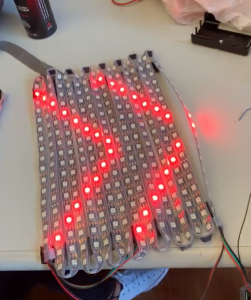
You get the idea…it was a struggle. But it turns out there’s a special glue called Silpoxy that works brilliantly, and tada…

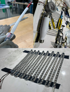
I also heat shrinked the LED strip wires for additional waterproofing protection.

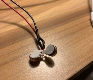
I also soldered the vibration motor component of the jacket as well, and will finish the integration before the demo. Next steps are to sew everything onto the jacket, and do a quick Raspberry to Arduino comm test via Bluetooth.

Sid’s Weekly Update March 10-23

Sid Lathar, A1 | Progress Report #5

Accomplishment:

Last two weeks have been spent debugging the app. The implementation was changed from using google maps API to smart-location-lib (https://github.com/mrmans0n/smart-location-lib)

This change was made because google maps API turned out to be very inflexible to tweak and required a lot of overhead.

Changes to schedule:

The progress is on schedule.

Upcoming work:

Apart from debugging the current implementation of the app, I plan to set aside time for making the UI for the app. I plan to get started on talking with the Pi and concretely describing what control signals we we need for customization of the notification system.

Mike’s Weekly Update, Mar 10 – Mar 23

Worked on figuring out programming the LED matrix and figuring out how to integrate the matrix onto the jacket.

In order to reduce memory usage on the Arduino, there had to be some clever tricks used to minimize the representation of the matrix images.

// bit representation of signal image on matrix
left_turn[] = { 
0B1000000000000001, 
0B0100000000000010,
0B0010000000000100,
0B0001000000001000,
...
}

void show_matrix (uint16_t M[], int r, int g, int b) {
  int curr_led = 0;

  for (int col = 0; col < WIDTH; col++) {
    uint16_t curr_bitvec = M[col];
    uint16_t mask = 0B0000000000000001;

    for (int row = 0; row < HEIGHT; row++) {
      if (curr_bitvec & mask == 1) {
        leds[curr_led] = CRGB(r, g, b);
      } else {
        leds[curr_led] = CRGB(0, 0, 0);
    }

    curr_led++;
    curr_bitvec = curr_bitvec >> 1;
  }

  // Skip LEDs that loop around at the corners
  for (int i = 0; i < NUM_LEDS_SKIP; i++) {
    if (curr_led < 300)
      leds[curr_led] = CRGB(0, 0, 0);
    curr_led++;
  }
}

By using a bit-vector instead of a naive integer matrix, we save (SIZE_INT – 1) * 256 = 992 bytes per 16×16 image.

An image from testing the matrix code:

Many possible mounts for the matrix onto the jacket, but the biggest concern is flexibility while maintaining integrity of the matrix to stay on the back. The most likely approach is to glue the matrix onto a clothe, which is then screwed or sewn onto the jacket. Heat shrink wrap and hot glue will serve as waterproofing for holes that have to be put into the jacket.

There is also a preliminary communication protocol that has been developed for the Arduino, which will be utilized when the Raspberry talks to the Arduino via Bluetooth.

Ben’s Weekly Update, Mar 10 – Mar 23


Saturday (16th)

Worked on the LKM, but after working a while decided to switch to pigpio instead of using an LKM because measuring pulse width requires two interrupt handlers, one for rising and one for falling edge, or requires checking the pin level within the interrupt handler, which apparently takes a uncertain amount of time. Using pigpio instead polls the GPIOs at a set frequency, while this still isn’t the most accurate, at least the error will be predictable and there is no need to mess with the kernel.

Sunday/Monday (17th/18th)

Worked further on the proximity sensors (ultrasound). Managed to get two working at the same time using my program interfacing with pigpio. Wrote the library to support six, which is the number we need. Am mildly concerned about the performance of the rest of the software running on the pi given the pigpio’s need for polling, but so far it seems like it is okay. Would consider the proximity sensors essentially ready for testing.

Tuesday/Wednesday (19th/20th)

Worked on the bluetooth connectivity between the Pi and the Arduino. Figured out how to configure the HC05 bluetooth module for the Arduino to use. Tested out the C libraries for the Pi’s Bluetooth connectivity.

A1 CycleSafe Weekly Update, Mar 3 – Mar 9

Updates

  • Almost lost our jacket after leaving it in 1303, but fortunately found it later. We will be more careful with it in the future.
  • Design review report completed. The report allowed us to put specifications and find data on a lot of things that we were mostly giving ballpark values for. Finding such data allowed us to have more confidence in the situations in which CycleSafe will be useful, and to make our requirements more precise in some areas, such as reaction time, braking distance, power requirements, and visibility.
  • Looking forward, spring break and the week after will probably just be grinding through the works of putting a prototype together.

Ben’s Weekly Update, Mar 3 – Mar 9

Sunday

  • Worked on design review report

Monday

  • Worked on the design review report.
  • Further refined the testing procedures. Interestingly one of the things brought up during the design review presentation will help a lot with testing. The fact that the speedometer will be connected to the Pi via an Arduino will enable easier testing because bicycle speed can be simulated simply by programming the Arduino to report a certain speed.
  • Noticed from looking at vehicle system testing procedures that generally very few tests are carried out. The primary metric is the time and distance at which the warnings go off, and whether warnings persist all the way through the danger. So the test were designed similarly to have the main metric for a successful test be the time-to-impact when the warning goes off and the persistence of the warning.

Wednesday

  • Started working on the Bluetooth interfaces between the Pi and the rest of the system. Worked on hashing out the communication needs and protocol between the Pi and the Arduino on the jacket.
  • Realised the communication needs between the Pi and the jacket are not very significant, and some communication requires guaranteed transmission while some communication just needs to get to the jacket quickly and can just be constantly transmitting. Will be interesting to see how the Bluetooth can be utilized for this.

Saturday

  • Starting working on the LKM for the Pi. Need to get interrupts going for the ultrasonic sensors.

Michael’s Weekly Update, Mar 3 – Mar 9

Accomplishments

  • Finished design review report
  • Acquired a jacket for the wearable component
  • Designed waterproofing for LED strips (heat shrink)
  • Designed a sew-on component for the LED strips instead of directly gluing it on the jacket
  • Preliminary sketches for possible 3D-printed waterproofing shells on the bike

Future

  • Prototype a few waterproofing shells
  • Build the jacket