
Worked on figuring out programming the LED matrix and figuring out how to integrate the matrix onto the jacket.
In order to reduce memory usage on the Arduino, there had to be some clever tricks used to minimize the representation of the matrix images.
// bit representation of signal image on matrix
left_turn[] = {
0B1000000000000001,
0B0100000000000010,
0B0010000000000100,
0B0001000000001000,
...
}

void show_matrix (uint16_t M[], int r, int g, int b) {
  int curr_led = 0;

  for (int col = 0; col < WIDTH; col++) {
    uint16_t curr_bitvec = M[col];
    uint16_t mask = 0B0000000000000001;

    for (int row = 0; row < HEIGHT; row++) {
      if (curr_bitvec & mask == 1) {
        leds[curr_led] = CRGB(r, g, b);
      } else {
        leds[curr_led] = CRGB(0, 0, 0);
    }

    curr_led++;
    curr_bitvec = curr_bitvec >> 1;
  }

  // Skip LEDs that loop around at the corners
  for (int i = 0; i < NUM_LEDS_SKIP; i++) {
    if (curr_led < 300)
      leds[curr_led] = CRGB(0, 0, 0);
    curr_led++;
  }
}
By using a bit-vector instead of a naive integer matrix, we save (SIZE_INT – 1) * 256 = 992 bytes per 16×16 image.
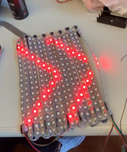
An image from testing the matrix code:
Many possible mounts for the matrix onto the jacket, but the biggest concern is flexibility while maintaining integrity of the matrix to stay on the back. The most likely approach is to glue the matrix onto a clothe, which is then screwed or sewn onto the jacket. Heat shrink wrap and hot glue will serve as waterproofing for holes that have to be put into the jacket.
There is also a preliminary communication protocol that has been developed for the Arduino, which will be utilized when the Raspberry talks to the Arduino via Bluetooth.