Team Status Report for 10/10

One of the significant risks we identified in our previous progress reports was a delay in ordering the PCB, and this risk has now occurred. When we looked at the price of the PCB, we realized we could not afford to order two boards (in case the first one did not work). This created an additional risk, since it left us with no buffer. We had to weigh the tradeoff between two options, sending the PCB out on schedule and risking a mistake that we could not recover from, or sending it out a bit late after checking it thoroughly. We ultimately chose to send the PCB out one week later than initially planned. Although this may set our integration back slightly, we decided it was the safer choice for the project.

No changes were made to our design. This week we finalized the design spec of digital hall effect sensors, which is represented in our PCB design. This decision will require a working CV element to the system to detect specific types of pieces. However, this is still in line with our current design. 

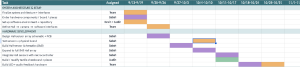
Schedule Update:
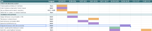
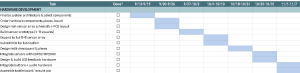
We moved the integration back by two weeks in consideration of the PCB delay. 

Photos from Sensor Testing:

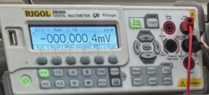
For both Analog and Digital Sensors we ran some distance testing (as cross-talking was our main concern). We ran each sensor with the magnet on top and in a 1/2cm distance.

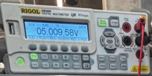
Directly on top of sensor (7cm = 0cm):
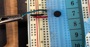
1/2cm away from sensor (7.5cm =0.5cm)
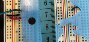
Analog Results respectively:
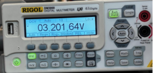
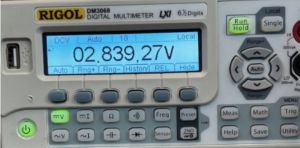
Digital Results respectively:
 

A was written by Justin, B was written by Kevin and C was written by Sabah.

Part A: The product solution we are designing will meet a specific need with consideration of global factors. 

Our project, while offering a much more accessible way to play chess for the visually impaired, is still limited in the global scope. Mainly because the braille and audio feedback features will be in English. This is a tricky barrier to cross in a single system because all major languages use a different writing system for the visually impaired. We suppose translated versions of the project may be created with little difficulty, although we aim to only help the English speaking visually impaired play chess more effectively. However, we do not require our users to be very tech savvy. The user interface on the web will be accessible to everyone on the local network, and on the device, we will have automated scripts that connect to known internet hosts upon startup. There will be equal accessibility to nearly everyone in the US and English speakers with minimal tech experience and access. With consideration to all global factors, language is a clear barrier that our project currently will not seek to expand on. Although with our target audience in developed, English speaking countries, we aim to provide a much more accessible way to play chess. 

Part B: The product solution we are designing will meet a specific need with consideration of cultural factors.

Our project is aimed to make chess more accessible to visually impaired individuals while also considering different cultural backgrounds and experiences of our different potential users. Chess is a pretty famous game played all around the world. While the rules are standardized, players may have different levels of familiarity with assistive technology and different preferences to how they would interact with the game. Additionally, players might even have different experiences and expectations for how chess is played. This may include how the chess community values fairness, independence, and equal opportunities. But in our current state of the world, because technology has progressed so much, online chess has become a popular mode of play. However, virtual play can often be limited to visually impaired players since they cannot see the screen or have any physical contact with the game. With the values of fairness, independence, and equal opportunities in mind, we are creating an accommodation for visually impaired players by incorporating tactile features so that they can participate in the same game as sighted players. Since chess is often played in a social environment, reducing these barriers between visually impaired and sighted players can help with play between friends, family, or even competition. By doing so, we are maintaining the social aspect of chess and encouraging inclusion within the chess community. 

Part C: The product solution we are designing will meet a specific need with consideration of environmental factors. 

In consideration of environmental factors we choose materials and designs to limit waste and conserve natural resources. The board surface is acrylic, which is both durable and scratch resistant, hence the board can last for years and be recycled at the end of its life. We are also considering 3D-priniting our chess pieces, in this case we will use a PLA. PLA is extracted from plant-based renewable resources and can be composted in industrial facilities. Our overall system is built with a modular design which allows users to replace the PCB, camera, speaker, or LEDs (neo pixels) individually instead of discarding the whole product. This design choice saves the raw materials used to manufacture these electronic pieces and additionally keeps the electronic waste to a minimum. Finally, the system uses little energy as the Jetson can run in a low-power mode, and the neo pixels only light up when giving feedback.  Lower electricity use means fewer fossil fuels burned to power the board, which helps conserve natural resources. 
Sabah’s Status Report for 10/10

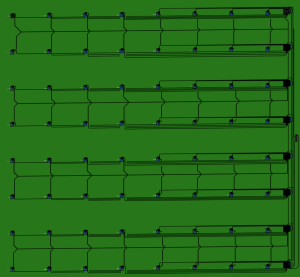
This past week, I finished the schematic and layout for the 8×8 PCB matrix. The layout took a lot of time because this was my first project in Fusion in about two years, so I spent time relearning the tools and wiring rules.

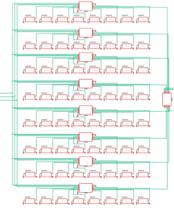
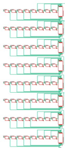
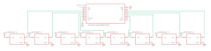
Here are the final schematic and the 3D layout:

8x8Digital SensorSchem

Our progress is slightly behind schedule. I decided not to send out the PCB before fall break, which technically set us back a full week. The PCB total came to about $364.50 (not including shipping), and we also need $25 for a stencil. That leaves roughly $30 in the budget for the NeoPixels, board materials, and chess pieces. While reviewing the order, we noticed a large $228.60 charge that came purely from the board’s size. We therefore decided to reduce the board from 2.5 x 2.5 inches per square to 1.1 x 1.1 inches per square. This lowers our cost and also helps our users, as a smaller board means less space for a visually impaired player to cover with their hands.

Over break, I have been shrinking the board and redoing the entire layout. To catch up, I rearranged some tasks. Instead of integrating the PCB next week, I will work on the front end of the website and on ordering and wiring the NeoPixels. By Monday, I hope to have the orders for the PCB and NeoPixels confirmed. For the rest of the week, I will figure out how the NeoPixels will work with the Jetson and begin work on the website.

Team Status Report for 10/3

Based on some of the feedback from the design presentation, it is going to be a priority for us to make sure that there is some benefit for the computer vision aspect of the project. As of now, it seems like it will be the most effective way to recover from corrupted game states, i.e. a hall effect isn’t triggered and the virtual state of the board becomes out of sync with the physical game. For the Jetson microcontroller, in the process of installing the operating system, we realized we need some form of persistent storage which needs to be ordered; the most affordable option seems to be a 128 gig microsd card. Once that arrives, we can boot the Jetson without the ISO image. This may set our software development back about a week, although we are confident that using a performant high level language such as golang will allow us to seamlessly manage concurrent processes safely and fast enough for our target requirements. Since go is also built with a nice networking interface, it should be also relatively easy to do the web backend with it; later down the line we need to decide if an on-device database or a cloud based solution will be best. Additionally, for the computer vision aspect, we are considering having the computer vision aspect to act as a secondary verification / recovery mechanism rather than having it as a primary means of detecting every move. We want to keep the hall sensors as the primary source for detecting board changes if piece classification is difficult to achieve under varying lighting or camera conditions.

One big feature we are going to add to our project is a website for logging the history of moves  which can be used by either a user who is able to navigate the web or a caretaker/ coach who could go through and analyze past games. This will be a simple add on to our software stack and requires no additional hardware or modifications to the overall software architecture. 

No changes have been made to our overall design since the design presentation, although some of the questions we received during our presentation have got us thinking about how the overall design may need to be refined. One of these possible changes is switching to a hardware-only product, by using analog sensors and magnets with variable strengths. We do want to create a smart chess board with as close to 100% accuracy as possible. So along with testing digital vs analog sensors this week, we will also try analog sensors with variable magnet strengths. If an analog hall sensing for determining piece types is very successful, we would prioritize development for this; it would also require ordering more magnets with more precise strengths and using some sort of ADC which would be integrated over I2C. 

As we just received the sensors and magnets we moved testing to this upcoming week. We have completed the full (8×8) matrix schematics for both sensors, so as soon as a sensor is selected we will move on to layout. 

Other updates to the schedule are to integrate ethernet much sooner, this would allow us to access our code base and download supporting software such as Jetpack 6.x for openCV. This will be completed with setting up the Jetson’s OS. Even though sensor testing and Jetson setup have shifted slightly, not all of the software tasks depend directly on the physical hardware so we are able to continue along the set schedule. During this time, we can also opt to use simulated board states to test board-state tracking, move detection, move validation, and move logging. Once the actual hardware is available, we can replace the simulated inputs with real sensor and camera data. 

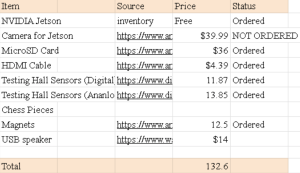
This is our updated price sheet & ordered products:

Sabah’s Status Report for 10/3

This week, I spent a lot of time practicing for the design presentation. In addition, I completed the matrix schematics for both the analog and digital sensor matrices. Here are the specs/connections of the sensor matrix: 

Analog Sensor Matrix: 

There are 8 sensors per row. Each sensor connects to a “mini” mux, and the 8 mini muxes feed into the master mux. The mini muxes share the same S0-S2 lines, while the master mux gets its own control lines.

For each mini mux:

A0-A1 Sensor0-Sensor7
S0-S3 Jetson GPIO inputs (control lines) (shared)
A Master Mux (first row mini mux A corresponds to A0 of master mux)

For Master Mux: 

A0-A1 MiniMuxRow0 – MiniMuxRow7
S’0-S’3 Jetson GPIO inputs (control lines) 
A ADC Input 
ADC Output  Jetson I2C Ports 

The Nvidia Jetson will have 6 GPIO ports for the designated control lines. The first three (S0, S1, S2) are connected to the S0, S1, and S2 ports of all the mini muxes. The next three (S’0, S’1, S’2) are connected to the S0, S1, and S2 ports of the master mux. The S0-S2 lines choose the column from each row, and then these 8 column sensor values, one from each row, go into the master mux. The master mux will then choose each row one by one and send each value into the ADC, then into the I2C ports of the Nvidia Jetson.

Here is some pseudo code for how the matrix will work: 

For c in range(0,7): # choose column for each row [c0, c1, c2, c3, c4, c5, c6, c7]^T

     For r in range(0,7): # choses the row from the set of columns   

          Return matrix[i,j]

Digital Sensor Matrix: 

In this matrix, there are 8 shift registers, one for each row. The shift register is a PISO, so it will take in all 8 sensor results in parallel and pass them out serially through one data output line (QH). This matrix works by daisy-chaining the shift registers together in order (SR0’s QH goes into SR1’s SER). The final output will be a serial line (from SR7’s QH) of 64 digital values, either 1 or 0. The first digit of the 64 will be for Sensor 0 in Row 0, and the last digit will be for Sensor 7 in Row 7.

In terms of the schedule, which has been changed for the design presentation, I am on track with completing my task for building the Hall sensor schematics (8×8), as shown above. However, our team task of testing the sensors and physical board has been pushed to next week because we just received the sensors on Wednesday and are not able to test them until Monday. I think as long as we complete the testing on Monday, I will be able to complete next week’s task of laying out the Hall sensor matrix after we have chosen which sensor to move forward with.

For next week, I plan to lay out the chosen sensor matrix and implement the LED matrix. Then, over the weekend, I should be able to order the full PCB.

Monday:

  • Run sensor tests
  • Discuss board dimensions

Tuesday-Thursday:

  • Layout board based on dimensions (LED & SENSOR)
  • Do final connection checks (power lines/register or mux connections/capacitors where needed)
  • Add to cart and calculate cost

Wednesday/Thursday:

  • Discuss with TA and send out the order if possible

I want to try my best to get the order out by Wednesday since the following week will be fall break and we don’t want to delay our pcb order. 

Sabah’s Status Report for 9/26

After a conversation with my TA, I realized the best course of action was to actually test out both sensor types rather than decide based purely on specs, especially considering potential magnetic cross-talk across adjacent squares. So, I have ordered a test-bunch (8 each) of both the digital and analog sensor alongside the exact magnets we will be using for the final project. Hence, testing will begin as soon as these materials arrive. In the meantime, we received our NVIDIA Jetson Orin Nano. This lets me establish exact hardware pin mappings which is helpful for considering how many GPIO ports I will have from the PCB. 

Since we are not sure about the sensors yet to stay on schedule, I developed the plan for two distinct 1×8 array PCB layouts. For our digital approach, I am pairing eight DRV5032FADBZR Hall-effect sensors with a 74HC165 Parallel-In/Serial-Out (PISO) shift register. I specifically chose a PISO register over a Parallel-In/Parallel-Out (PIPO), because a PIPO register has 8 output lines, while the PISO register has an output of a single serial data line. When scaled to an 8×8 matrix, daisy-chaining eight shift registers end-to-end allows us to read all 64 squares across the board while only using 3 control lines (data-out, clock, latch). 

For the analog validation design, I am pairing eight DRV5055A1QDBZR linear sensors with a CD74HC4051 analog multiplexer. Using three digital GPIO selection lines we can choose from (000 to 111) for the multiplexer choosing between sensor 0 and sensor 7. Although Jetson Orin Nano doesn’t have built-in analog-to-digital converter pins, so the multiplexer has to be routed to an ADC chip (converts analog to digital number) before transmitting the data to the Jetson over I2C or SPI pins. To scale this approach to an 8×8 board, I plan to implement a two-stage multiplexing. Each row of 8 sensors gets its own CD74HC4051 analog multiplexer. The three digital GPIO selection lines will be in relation to the columns, so if 111 is chosen then the column 8 sensor for each row will be selected. Then these 8 outputs go into a master multiplexer which is chosen through another three GPIO selection lines. This essentially results in a nested for loop one for the column, and the other for the row. 

I am on time with the schedule, as we have ordered all necessary components and I have designed the plan/schematic for the 1×8 architecture. I should be done with the PCB 1×8 prototype by next week. In addition I will be presenting for the design presentation next week, so I will be spending some time preparing for that. I hope to deliver that well :). 

Digital:

Analog:

When implementing the ADC (ADS1115IDGSR) , port (A) from the multiplexer will be allocated to the ADC.

Team Status Report for 9/19

One of the biggest risks to the project is a delay in ordering or receiving the PCB, as well as the possibility of the PCB not working correctly. To reduce this risk, we will test the components on a breadboard and build a small 1 × 8 prototype before ordering the full 8 × 8 PCB. If problems occur, we can continue software testing with the prototype while correcting the PCB.  Another significant risk is the reliability of the computer vision system. Things like lighting, camera position, shadows, or similar looking pieces can cause the system to incorrectly identify the actual board state or identify a move being made. To reduce this risk, we will have to test the camera under different lightning conditions and use a fixed camera position. We can also compare the detected board state with info from the Hall effect sensors to improve reliability.  The main software risk that we determined on was keeping the physical board state synchronized with the digital chess state. Incorrect detections, missed moves, or communication errors between different components might cause the digital representation of the board to be inaccurate. To manage this risk, the software will validate detected moves against the current board state and chess rules before updating the game. Individual software will validate detected moves against the current board state and chess rules before updating the game. 

No changes have been made to the main system design since the proposal presentation. In terms of schedule update, the component delivery task has been moved from last week to next week. This gives us time to review our order plan and component choices with our TA before submitting the order. 

Sabah’s Status Report for 9/19

This past week, I spent time finalizing the system’s circuit architecture, researching components, and planning my approach for the PCB. The final PCB board will use an 8 × 8 matrix of Hall-effect sensors and LEDs, but I decided to begin with a 1 × 8 prototype. This will allow me to confirm that the sensors work properly and meet our 98% accuracy user requirement before ordering the complete board. A major concern is crosstalk, where a magnet may activate a sensor on a neighboring square. I compared linear analog sensors, which measure magnetic-field strength, with switch sensors, which produce a simple ON/OFF output. Although analog sensors could help identify which sensor has the strongest reading, they would require more processing and could increase latency (another user requirement). Since both accuracy and response time are important, I decided to use a switch sensor. I selected the 20 Hz DRV5032 digital omnipolar switch because it is sensitive, responds quickly, and is omnipolar. I also want to test the sensors physically before finalizing the PCB, so I plan to purchase/find SOT-23-to-3-pin DIP breakout boards. These will allow me to connect the sensors to a breadboard and test the complete 1 × 8 setup using an Arduino. 

I am slightly behind schedule, although I completed this week’s main tasks: finalizing the circuit architecture and selecting the major components. The delay is mainly because I have not yet submitted the component order form. To catch up, I plan to meet with my TA on Monday to review my approach and component choices before submitting the form. Once the approach is approved, I will submit the order immediately and begin the PCB design while waiting for the components to arrive.

Next week, my main goal is to complete the 1 × 8 PCB array design by Friday. This includes designing both sides of the board, with the LEDs on the top and the Hall-effect sensors on the bottom. Since I have previous PCB design experience, I believe this is a realistic goal. In parallel, I also want to begin working on the design presentation, which is due next weekend. I will be presenting on behalf of my team, so I want to discuss each part of it with my teammates.