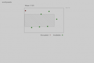
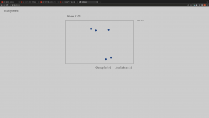
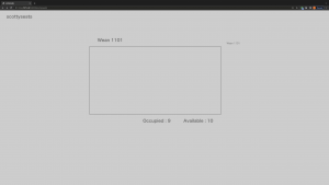
This week, I wrote the function that handles requests from the CV module and store it in a JSON format file, and integrated my code with Mehar, meaning that no like before, the server tells the CV module to run when the client requests, and then read from the data file the CV module outputs, now the server will only have to handle requests sent from the CV module and then update it in the JSON database file with the JSON data the CV module sent me, and handle requests from the user and send the whole database to the user. This way, the server and the CV module can run seperately. This has been tested out and made sure it work, as we spent hours debugging and made sure we can send data in a local network.
Additionally, for the spatial accuracy metrics, as explained below, it is better for us to change the metrics. The loss function we are going to use is the quadratic loss function, namely, the
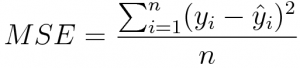
where, as suggested by Adnan, yi is defined to be ratio of “the y or x coordinates of each chair to the table in pixel values of the predicted image”, dividing “the y or x coordinates of each chair to the table of the overhead true image “. This ratio should be similar, thus we use the “yi hat” to imitate the true value, which is the average of all the ratios as defined above. This the larger the MSE, the more it deviates from the “normal” value, the more loss it has.
Perspective Adjustment:
Apply a perspective warp to a picture, the basic thing we need is the coordinates of the 4 points of the shape we want to warp.
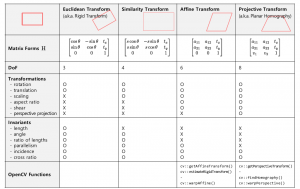
Inside the CV library there are ways to do this. For example, cv2.getPerspectiveTransform, along with cv2.warpPerspective, or utilizing functions such as cv2.findHomography.
The problem with this is that the output is an image, thus it has to be perspective adjusted before feeding the image into the image recognition algorithm, in other words pre-processing. Then, in this case, it would be hard to recognize the objects. If we put it in post-processing, then it is hard to get the exact coordinates of the warped image.
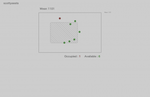
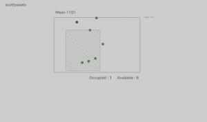
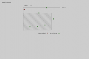
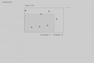
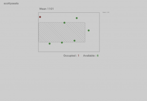
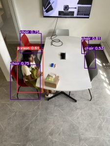
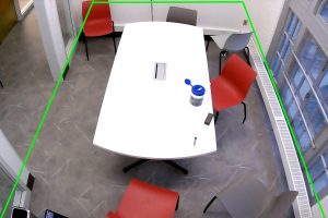
More over, to warp it in the first place, we need to get the 4 corners, and to get that, we need to find the 4 corners of the ground. Additionally, applying warp if we crop it to only include the ground is not enough, because chairs have heights, so if we only crop it to include the ground, some chairs will be cut off. We have to cut it so that the upper chair and lower chairs are included, this means that some of the wall must be included. This means that error is inevitable in applying perspective adjustment, as shown below.
Since the lower 2 points are not visible, we assume it is the lower 2 corners of the image. For the upper 2, there are basically 3 way to gain it:
- Hardcode it when setting it up
- Detectron2 image segmentation
- edge detection
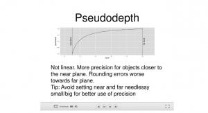
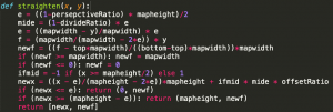
1. First one is what we have now. I updated the algorithm this week. Before, the x coordinates are stretched to the side to form a rectangle, but the y coordinates, since the more you go into the image the more distance the same amount of pixels represent, I applied a linear function in the real distance it represents according to the y coordinate of the point. This week, realizing that 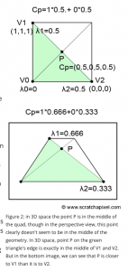
according to the above image, the “P” point is always the real center of the plane, that means that when the y coordinate is located at that point, in other words the ratio of the upper and lower edge of the trapezoid times the height of the image, the adjusted y coordinate should be 1/2. According to this, we form a y = ax^2+bx+c function and solve for it to gain a function that maps y coordinates to real y coordinates, with then x = 0, y = 0, x = “P”, y = 1/2, x = 1, y = 1.
2. Detectron2, however, might be an overkill to our case. I spent lot of time trying to implement detectron2 but was stuck on CUDA. Anyways, since detectron2 is trained on COCO dataset, it does not include the ground category, thus to use it we have to gain training data on floors to detect the grounds. Additionally, the standard output 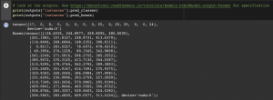
as shown here, is similar to YOLOV5 – it only includes the bounding boxes coordinates. To access the exact outline, we have access the variable where the outline is stored, while it is stored in a “Tensor” format. Then, to utilize that to gain the corners of the ground, we will have to change in a cv2 readable format, in other words, a “numpy array” format, then some analyzation could be used to simplify it and potentially gain the corners. For example, cv2.approxPolyDP() could help us in shaping it into simple shapes, then the 4 corners can be easily retrieved. However, a more fatal problem is that, even if we have all of the above realized, our ground doesnt have a boundary, which will be shown in the next section.
This also rules out the possibility of applying feature recognition, a common way when working with homographies.
3. 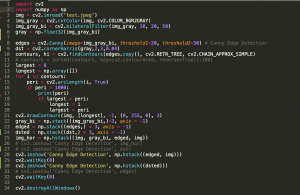
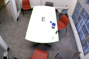
as shown in the image, I played around with CV methods endeavoring to get the outline of the upper 2 corners of the table or ground.
We first convert it into grayscale, and then apply cv2.bilateralFilter to accentuate edges but blur the rest, a better version of Gaussian blur in edge detection.
Then, I ran Canny Edge Detection and Harris Corner Detection, cv2.Canny and cv2.cornerHarris respectively.
Then, I look for the longest edge, however, I was stuck here as no matter how i adjust the numbers, the edge of the table is not continuous. To fix this, I adjusted the Canny Edge Detection so that it detects even the smallest edges but this will just not form an enclosed edge of the table. Another way is to merge close up edges, but this means that all the chairs and bags will also be merged into the edge.
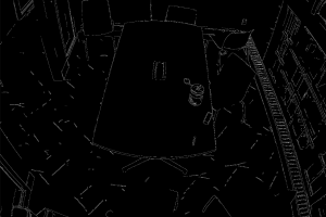
Canny Edge Detection
Canny Edge Detection Longest Edge
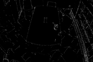
Harris Corner Detection
Additionally, as you can see the ground doesnt have a clear boundary. Also, since the table is just part of the room, if we rotate the table, that means that the corners of the tables will change, and thus the ratio of the upper and lower half of the trapezoid will change, thus meaning that the perspective adjustment will change, leading to unpredictable results.
As above, the most stable way is definitely hardcoding the ratio of the upper and lower edge, or another good way to think about it is to gain the cos angle of the line of the edge of the table, since we are applying the perspective shift to the whole image instead just the ground or just the table anyways.