Vikrams Status Report for 10/23/2021

Last week we focused on making an MVP housing out of foam core and populating it with a few components needed to do thrust testing during a drop. We had our first test with it last week, which failed due to spinning, and hope test again next week. We also performed tests that showed that our directional antennas were not a viable perception method because of their lack or resolution and inability to tell direction with enough accuracy. This involved around in a fixed radii and seeing if the antenna could discern if the beacon was in the “center” of it’s beam path.

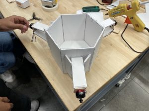
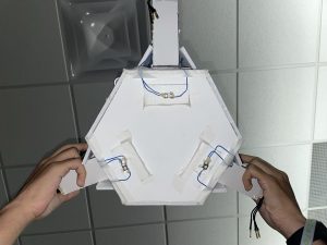
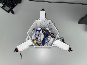
This week, I focused on improving the state of.our MVP, with new code for our Arduino test platform, an ultrasound sensor to detect when to stop when our device is above the ground, and a new protoboard where many of our connections were soldered in order to make sure everything is secure now in the event of flipping or spinning. This new board houses I/O in the form of buttons to start and reset the motor spinning up process, in addition to the ultrasonic sensor. Additionally, I’m starting to model our new design for the housing that is based on the hexagonal shape that we prototyped out of foam core. This will hopefully be lighter than our original 3d printed design, and easier to manufacture (time-wise) as well. Some key issues we found with our original design was the print time and the estimated weight in PLA plastic that it would take on. The next steps are to use this updated test platform for another powered drop test, and hopefully for a perception test with our new camera system soon. This camera system will detect a black and white marker placed on the ground and use that to do it’s direction-finding. This way the control method doesn’t have to change much, just the perception method turning an image into a direction to travel in instead of an antenna array. This will hopefully allow us to do more fine-grained control as well, should we need it. Currently, we are on schedule and the new and updated housing will be continued over the next week in order to have our final build housed in a weather-proof container. The indicator LEDs and I/O buttons should also make setting up/ using our system significantly easier.


Lahari’s Status Report for 10/23/21

During the week of Oct 10-16 we set about creating the MVP for our project, while working on the design report. This version of the device was made of Foam core, because the material is lightweight and easy to modify. I helped fabricate the housing by tracing, cutting and gluing various pieces. We decided early on that three propellers was the minimum necessary to achieve omnidirectional movement, so we chose a hexagonal shape for the body. This would achieve less air resistance and a symmetrical design. The design had three arms to extend the propellers outwards, so that airflow would not be obstructed by hitting the sides of the housing. The goal was to see how far our propulsion system could move the object during a drop test. The week culminated in another drop test which was unsuccessful, because the device spun during most of the fall. 


Meanwhile, we performed final tests which helped us rule out directional antennas as our perception method. The new WiFi board had arrived, so we tested it out with the directional antenna. Daniel and I went out to the grassy area outside Hamerschlag to find at what distances and angles a phone hotspot would produce higher RSSI. The signal was stronger in a usable horizontal angle of about 30 degrees, but only within 20 feet. The range of the vertical angle where the phone could be detected was very narrow. Lastly, the back of the antenna also had some range where the signal was as strong as in the front. This meant the antennas were not practical for perception for much of our use case, it would not be possible to detect relative direction based on these antenna data. At the end of the week we decided to switch to computer vision instead of antennas for perception. 


During the week of Oct 17-23 we continued working on our device. I am now in charge of computer vision instead of signal processing because we have switched to cameras. We decided to use circle detection, so that the use case would remain simple. The user would only have to place a circle marker on the ground. I implemented a circle detection script in Python with OpenCV. The script converts the frame from a camera feed to black and white, applies median blur, then HoughCircles (from cv2 library). The result was the coordinates and radii of the circles in the image. Daniel and I integrated this code with the Raspberry Pi camera, and found that the detection was robust. What remains to be done is to find out the latency associated with the code, we may consider using C++ to remove some of it. We also want to go outside and see whether it works at a distance of about 40 feet and with different lighting conditions. I may have to adjust the parameters, such as circle radius and blur kernel, based on these tests.

Team Status Report for 10/23/21

Oct 10-16:

This week, we worked on creating out first prototype as a way to test our propulsion, then our perception after we determine our propulsion works. We chose foam-core as our material so we could rapidly prototype for cheap. Below is the completed housing with the motors attached:

We then needed to run the motors. At first, we tried a Raspberry Pi to generate the necessary PWM signal; however, we found that the Raspberry Pi only has 3.3V logic, whereas the ESC required 5V. We moved to an Arduino Uno for the meantime as it has 5V logic, but are planning to use logic-level converters to step up to 5V. We also decided that for testing purposes, we should have a start and stop mechanism. For starting, we used a single button that once pressed, started the device after 30 seconds. For stopping, Vikram suggested 3 buttons on the bottom of the device that stop the device once pressed under its own weight. The device looked like this:

After this was done, we put all the electronics inside and were ready to test the motors. Since it was raining, we had to test the thrust indoors first, so we tied string to the device as one of us stood on a ladder. We found that the motor at 100% had  power to move the device (total weight 1.4 pounds. without payload). Here is the link to the video: Motor Test

At this stage, we also received a new ESP32 Board that we could directly connect an external Antenna to without any soldering. This way, we could actually test the performance of the directional antenna and decide if it is usable. We found multiple issues with the antenna approach:

  1. The antenna had two discernable peaks at the edges of the 30 degree beam width, such that you could not discern from the RSSI if you were to the left or right of the antenna (RSSIs were equal at these two points).
  2. The middle of the beam width had a trough in RSSI, such that the RSSI read right in front of the antenna, was the same as the RSSI read outside the 30 degree beam width.
  3. The back of the Antenna resulted in a peak in RSSI similar to being in front of it.
  4. The Antenna was only able to get reception up to a range of 20 feet. Our drop height is in the range of 30-40 feet, meaning that for the first half of the drop, the perception system would not perceive much.
  5. The vertical sensitivity of the antenna was very low, meaning  as the signal source moves with respect to its vertical position, RSSI changes only towards the very middle of the sweep. This is crucial as the device will be falling downwards.

To mitigate this, we have decided to move forward with a CV based approach using a camera, and a circular visual market.

Oct 17-23:

This week, we dropped our device with motors for the first time to test the propulsion. Here is the video: Drop Test.

We found that A. the unsynchronized drop caused a spin in the device and B. the parachute set up created even more spin. Due to how the motors are set up, any small amounts of spin will cause the device to continually spin as the motor fires. To mitigate this risk, we have shortened the parachute slack, and attached the parachutes properly using carabiners with holes in the housing (instead of tape). We must now drop it again to see if this fixes the spin issue. If this does not, we plan to design an arm system that will place the parachutes further from one another in a square formation, with the addition of two more parachutes (which we have ordered)


Lastly, as we moved to a CV based approach, we ran the Hough circle detection algorithm on the Pi and found that it is successfully able to detect circles (5 cm radius from a 1 meter height). We plan to print a 0.5 m radius circle and test the detection from the Pausch bridge next (0.5 m radius found from scaling up the 5 cm example to the height of the bridge). According to how well this works, we may need to use a larger circle, or tweak the algorithm by changing some sensitivity parameters.


Daniel’s Status Report for 10/23/2021

Oct 10-16: 

During this week , I mainly assisted the team in constructing our first prototype. We chose to build it from foam-core, so I cut out some of the shapes needed to build the different parts of the device (such as the arms and sides). After constructing the basic skeleton, I wrote an Arduino program to control the device for preliminary tests. This involved  connecting some buttons to the Arduino on a breadboard, and writing code to generate the necessary PWM signal to run the brushless motor. We had two sets of buttons. One button was used to start the motor, and three buttons on the bottom of the device were used to stop the device when it hit the ground. After I tested this worked on a breadboard,  I then soldered wires to the buttons and with the help of the team, attached these and the remaining electronics onto the housing. We then ran some tests as a team indoors (as it was raining) to see if the motor was able to move the device, and it was (explained in the team status reports with videos). I also began thinking of how to create the vectorization algorithm for the control system, and with the help of Lahari and Vikram in the realm of matrices, we landed on an approach that I can begin to implement, keeping me on track,


Oct 17-23:

This week was mainly focused on testing the propulsion of the device outdoors, and seeing what modifications we needed to make. We worked as a team to figure out how to mount the parachutes to the device, and went out the Pausch bridge to drop it. Lahari and I dropped the device from the bridge, while Vikram was at the bottom in order to catch it. The results and consequences of our findings will be discussed in the team status report. Due to the rain, it was difficult for us to do more testing outdoors. At this point, we also found that the buttons placed on the bottom of the device to stop it were not ideal as they could sometimes not be pressed (if the device fell on its side, or on grass), so we decided to move to an ultrasonic sensor that would stop once the device was close enough to the ground. We have also moved to a camera approach for our perception (discussed in group status report), so I helped attach the ultrasonic sensor and camera to the bottom of the device, and cut a slit to allow the wires through. Lastly, as we needed to test the camera on our Raspberry Pi, we used an OpenCV example script to run the Pi Camera, and I helped integrate Lahari’s circle detection algorithm (which we will use to find our target) onto to the existing python script. We found that the script runs fairly well, but more testing needs to be done to determine the true latency of the script. The results from this script will be fed into the vectorization algorithm that I’m working on.

Daniel’s Status Report for 10/9/2021

This week, I helped the team create a test setup for the motor to measure the thrust. We initially had the motor set up on a flat piece of wood with legs, standing on a scale so we could measure thrust; however, the lack of space under the motor did not allow the propellers to move enough air, and no thrust was generated. I suggested that we should attach the motor to an arm extending over the test setup such that the motor had clearance. When we did this, we were able to actually measure the thrust of the motor. In preparation for this, I soldered wires for the motor controller, and helped put the overall construction (drilling, screwing, gluing).

I also did research regarding potential boards to connect our antennas to, to be able to measure RSSI. We had trouble with our ESP32 board when connecting an external antenna to it; we had to move an SMD resistor to change the antenna from onboard to external, which proved difficult and resulted in a solution that could effect our antenna reading (excess wire, solder). So, I found a board that required no DIY work (SparkFun Thing Plus). Once we get the board, I will be able to run more Antenna tests to gauge the antenna sensitivity more accurately; Specifically, I will need to test multiple antennas to see the difference in RSSI observed from different directions (before we get multiple Antennas, I plan to use a single spinning one to replicate multiple ones). In the meantime, I will begin working on the design for the vectorization algorithm which takes in RSSI and outputs PWM duty cycles for each of the motors, so I continue to be on track for my tasks.

Lastly, in considering other perception methods (if the Antennas do not work sufficiently well), I brought an 8×8 Thermal Camera I had lying around for an Arduino to test if it is a feasible method. I soldered and wired it up to test it. However, the low resolution mixed with potential damage to the camera meant the data was not too useful. Additionally, the small sensor size meant that the range was highly limited. If we wanted to test this perception method again, we would need to acquire a higher resolution thermal camera.


Team Status Report for 10/9/21

This week the items that we ordered last week arrived. This allowed us to do more pretests, namely the thrust of our propellers and the drop speed of a weight with a parachute. On Thursday we prepared these tests at the lab. First, we filled a tupperware container with water to weigh about 1kg, since this is the expected upper bound for our device weight. We then attached the two 54-inch parachutes to the container and secured it with the duct tape. 

We walked these items over the Pausch Bridge, and tossed them off, while one of us recorded a video of the drop from a distance. The video indicates a time from release to landing of about 3.8 seconds. This is approximately the amount of time during which the device can operate, and it is very close to the amount of time we anticipated. Video

Meanwhile, we also began creating an apparatus to measure the thrust of the motors and propellers. The apparatus consists mainly of a motor and propeller mounted to some wood, placed on a scale, with a battery and PWM generator. An image of the full setup is attached below. With the propeller at full speed, the change in weight indicated by the scale provided us with a verifiable measurement of the thrust: 400g. Our test was not ideal, and it appears that some of the thrust was exerted onto the scale, because the arm may have acted as a moment arm. To remain on schedule we are accepting these results and moving on. As a form of early risk mitigation, we are researching thermal cameras as an alternative to antennas.

Vikram’s Status Report for 10/9/2021

I continued to work on the CAD modeling this week for the housing, as well as getting the motor and controller test working. From our test, the results have shown some improvements that need to be made to the design, where our motors are mounted. In order to make enough thrust to move, there needs to be a significant amount of space between our motors and the housing. Also our motor controller needed to be factory reset and have the throttle range calibrated in order to work correctly. I did some research into alternative methods of perception, in the event that our antennas do not work as intended. So far, thermal cameras seem like a potentially promising idea, as they have low resolution for low processing time, and do not require infrastructure or daylight to work, because of the heat of a body or fire/flare. So, I did some research looking into them and specifically the FLIR Lepton camera that could potentially work with a big/hot enough source like an open fire (or for testing a heat gun/heating pad) . So far we are right about on schedule, but the CAD design is not finalized yet because of our recent findings on motor thrust. By next week I would like a relatively finalized CAD design ready and hopefully have it printable/ready to be 3D printed.

Lahari’s Status Report for 10/9/21

This week I spent time working on the pretests and the design document. For the design document, according to feedback I adjusted the block diagram, because I forgot the motor controllers in the presentation. We did a drop test and a test of propeller thrust to conclude our pretest phase.

The drop test gave us an idea of the amount of time available for onboard computations and movement. The propeller test would verify the 1kg thrust metric from the product listing. We put together the parachute and the weight and headed to the Pausch Bridge, where I released the items from the top, while Vikram waited below to retrieve and ensure no passers by. Daniel filmed from the street exit on the fifth floor of the Gates Center. 

The propeller test was somewhat successful, though we had some problems with the PWM generator while getting started. All in all, we completed the tasks on our schedule that require our combined attention. My individual task during this week and going into next week involves digital filtering of the RSSI data we collected last week.

Daniel’s Status Report for 10/2/2021

This week, in preparation for our Design proposal presentation (which I will be presenting), I helped with some of the content on the slides while also preparing what I should say. I wrote notes for each slide in the form of main points, and rehearsed the presentation multiple times. On the technical slide of the project, I helped program the ESP32 board, and connect it with our new directional antenna to find out if direction sensing can work using our approach. This involved setting up the Arduino IDE to work with the ESP32-CAM board, and using the WiFi library to gather RSSI data.

I helped run some preliminary sanity checks indoors to see if the Antenna was behaving as expected. We then moved outside where I helped collect the RSSI data for different test cases of our antenna (such as different angles of the WiFi beacon from the antenna, different distances from antenna, as well as orientation and tilt of the antenna). I then moved this data to Excel and plotted it to find out if there was a discernable peak in one direction so we can use it for direction finding. We ultimately found that there is a peak of signal strength of around 30 degrees when the antenna is placed horizontally, and that it had enough resolution such that we could tell the RSSI peak from around 30 feet away until right up to the antenna. Now that we have obtained this data, I am starting to think about the specifics of the propulsion algorithm that will take the antenna’s RSSI data to output various PWM values for each of the motors. My team also suggested that we may need to consider a filter to pre-process the data.

When the parachute and motors arrive next week, we will begin testing drop speeds, motor thrust as well as do additional testing on the antenna in different configuration

Vikram’s Status Report for 10/20/2021

This week, I worked on the design of certain aspects of our project. Specifically I focused on the new CAD model of our device, using some of the specific components that we ordered like motors, propellers, controllers, and raspberry pi zero. I also added some of the housing design elements we proposed, like a domed bottom for aerodyamics and fins to help stop spinning.  This CAD model will help us get a better idea of how everything will fit together, and the physical design that will be 3D printed. In addition, I helped edit the design presentation, and added in figures and drawings that are useful to help illustrate and exaggerate points to the viewers. We also developed a test fixture together and ran some pre-tests to see if the directional antenna is a viable option for direction finding. Our initial results are promising, but further testing is required in order to truly determine how reliable direction sensing with the antennas will be. This progress is in-line with our schedule, and as long as the antennas remain viable this will put us in the correct position for next week, as long as the parachutes and other items arrive on time. In the next week, I hope to have a drop time test completed, as well as more antenna testing and if possible (will happen last or the following week probably) at least 1 motor drive test, in order to measure approximate thrust.