Team Status Report for 12/4/21

Over the past week we have been working on the two pending tasks on the schedule: final testing and housing. We laser cut the remainder of the pieces and attached them to the 3d printed arms and brackets we made before the break. The body is pretty sturdy and awaiting drop testing, but as a form of risk mitigation we still have our prototype. The new housing unit is completed (video) so the only other task in our schedule is to finish up testing. In today’s round of testing we had four trials:

Min: 1.27 m

Max: 2.84 m

Mean: 2.40 m

Median: 2.74

We have been making adjustments to the code as we go with our trials, like adjusting binary threshold and thrust from trial to trial. We have also been able to reduce the latency by removing a delay in the function that sends data to the Arduino via serial. The movement is much smoother after we made this change. Our goal for the next week to finish drop tests by Tuesday so we can switch focus to shooting our video and working on the final report.

Team Status Report for 11/20/21

This week we wanted to test the propulsion fixes we worked on last week, since we got the chance to charge the battery fully. With the weights also redistributed and the thrust at 75% we were able to produce some movement. It was particularly windless that day, so the motor off drop is directly below the dropping point.

Pictured: Drop with motor off, 50% thrust, 75% thrust

On Monday we did a camera test to rule out the fisheye Raspberry Pi camera against a equirectangular Logitech camera. The camera is a bit heavier but the detection is a lot better that the Pi camera. Once we chosen the Webcam, we also varied the the resolution to see the tradeoff between detection rate and fps. With 480p we had 62% and 3.9fps with 720p we had 46% and 1.7fps. We will likely repeat this test, because the change in lighting between trials was substantial which is why the detection rate is not higher like expected, but the frame rate is clearly to low with 720p. Any smaller resolutions compromise detection and larger ones compromise frame rate.

The rest of the week we spent planning and fabricating the new device housing. We made several CAD models, laser cut most of the body, but were unable to 3D print because of time. We will be 3D printing the arms on which the propellers attach, and this will be a priority next week.

Team Status Report for 11/13/21

This week we finished up the interim demo and continued testing to improve the propulsion system and computer vision. At the end of last week, we finished integrating the Raspberry Pi with the Arduino in the prototype we have been working with. On Sunday we finished the integration phase by calibrating our software to respond to a circle target placed below the device (where the camera is pointed). We found that the camera feed was off center. That is, the center of the frame was not exactly directly below the camera. This would have been an issue later because when the target is near the frame’s center, we want to fully deactivate the motors. Another issue was that we had to assign one of the motor directions as the origin, or 0° point. As it was, the direction derived from the computer vision was not synced to the direction of the motors. To correct for both of these problems we added an offset of about 30° to the angle and 200px to the center inside the circle detection script. 

After the demos were completed we prioritized working on our propulsion thrust because it was not enough to get our device moving enough. We fabricated another thrust testing apparatus to measure the amount of thrust being produced. 

The propulsion is exerted down onto the scale and originally measured 330 grams. We theorized that the low gauge of our wires was inhibiting current from the ESC to the motors. When we replaced these connectors with thicker ones, the thrust was 400 grams. Another measure we took was adding 600 grams of gravel to the inside of the device, as a weight. This was meant to increase the tension in the parachute straps, to reduce swinging. We did a drop test with this setup and the swing was reduced, but our propulsion was still insufficient. We found after returning to the lab that the battery was low on charge. We will be trying again with increased propulsion tomorrow, weather permitting. 

Thrust test with low vs high gauge wires:

Lastly, we held the camera over the Pausch bridge to see if our detection would work after all the changes we made over the past two weeks. This week, we reduced the shutter speed to reduce motion blur. This change increased the detection rate from about 35% to about 90% in the indoor setup. We found that the circle was too small in the camera feed when held from the 43’ height. We are working on two avenues to fix this. One is to print a 2-meter circle instead of the 1-meter target we have now. The other method is to enlarge the usable portion of the fisheye image or correct it to be equirectangular. Our mitigation strategy for this area is also to start testing on a USB webcam, which will altogether remove the issues we face with a fisheye lens, but add more weight. 

Note the lack of motion blur with the faster shutter speed, both frames taken mid-swing:

1500 microsecond exposure time

9995 microsecond exposure time (circle is not detected!)

Team Status Report for 11/6/21

This week, we completed several more drop tests and prepared the interim demo for next week. We inferred from last week’s tests that there was not enough thrust to move the 3 meters that we wanted. Our idea then was to use two motors on each of the three sides instead, to hopefully double the thrust. At a TA’s suggestion, we also acquired larger propellers as another way of increasing the thrust. The thrust tests, done on a scale, showed 600 grams with double propellers. It was approximately 600 grams with the large propellers as well, but these were not meant for the motors we had so they couldn’t be installed properly without vibration.

We did a few drop tests on the double propeller arrangement we put together last week. We repeated the tests several times, each time adjusting for different variables. The first time around, we noticed there was swing so we changed the Arduino code to start after the drop began. On later tests we had to address spin and lack of movement. We were unable to modify the design so that the propulsion system would move where we wanted. This is the area of our project that is the most uncertain at this point. To mitigate risk, the next time we get the chance to do a drop test we want to add balanced weights to the inside of the device. We think that a persisting problem is the lack of tension between the parachutes and the device. With this change movement will not be impeded by swing or spinning. Video

For our interim demo, we set up an apparatus that will suspend our device 1.3 meters off the ground, while we move around a target image of 10cm diameter below the camera on the bottom. This models our actual 13 meter drop height against a 1 meter target diameter. We will show that we can activate the propellers in the correct direction based on the target’s relative location.

Team Status Report for 10/30/21

This week we improved on the drop test from last week, the problem was that the device spun during most of the descent and the parachute ropes twisted together. To fix this, we shortened the ropes and mounted them on opposite sides of the top. This solution would ensure that the parachutes were separated during the whole drop. Spinning would otherwise interfere with our perception method, which ultimately determines the relative angular position between the device and the target. When we tested this version on Monday there was no noticeable spinning. 

We then shifted our focus on movement from our propulsion system. We wanted to see how far the propeller at full thrust would move the device. Wednesday was more appropriate for the lateral distance test, because it was not windy. By this time, another set of parachutes had arrived, so we added a third parachute to the body, so the drop time would be longer. The test showed an additional parachute did not achieve this. We would like to test this a few more times before we reject this option, especially because there is more weight that needs to be added, including the payload and extra propulsion. 

At full thrust, the device could not move three meters laterally, a key technical requirement of our project. We decided that each arm of our device should have two propellers instead  of one. We already had an extra motor, ESC, and propellers, so we put double propellers on one of the arms. We plan to test the new thrust capability on Monday, and decide whether to order more parts.

Meanwhile, we conducted a few tests on the circle detection code. We found the 1m diameter circle (pictured below) was detected between 48 feet and 10 feet of distance. It is approximately the same indoors and outdoors. We plan to find the angular range of detection at a few fixed distances next week.

Team Status Report for 10/23/21

Oct 10-16:

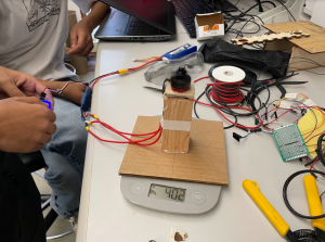
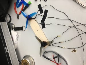
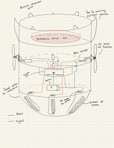
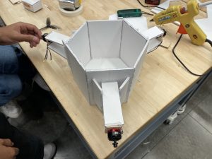
This week, we worked on creating out first prototype as a way to test our propulsion, then our perception after we determine our propulsion works. We chose foam-core as our material so we could rapidly prototype for cheap. Below is the completed housing with the motors attached:

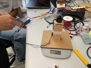
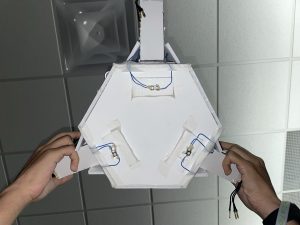
We then needed to run the motors. At first, we tried a Raspberry Pi to generate the necessary PWM signal; however, we found that the Raspberry Pi only has 3.3V logic, whereas the ESC required 5V. We moved to an Arduino Uno for the meantime as it has 5V logic, but are planning to use logic-level converters to step up to 5V. We also decided that for testing purposes, we should have a start and stop mechanism. For starting, we used a single button that once pressed, started the device after 30 seconds. For stopping, Vikram suggested 3 buttons on the bottom of the device that stop the device once pressed under its own weight. The device looked like this:

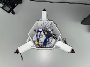
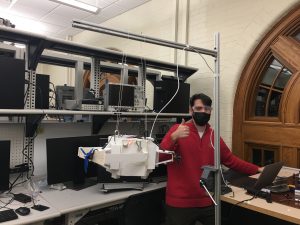
After this was done, we put all the electronics inside and were ready to test the motors. Since it was raining, we had to test the thrust indoors first, so we tied string to the device as one of us stood on a ladder. We found that the motor at 100% had  power to move the device (total weight 1.4 pounds. without payload). Here is the link to the video: Motor Test

At this stage, we also received a new ESP32 Board that we could directly connect an external Antenna to without any soldering. This way, we could actually test the performance of the directional antenna and decide if it is usable. We found multiple issues with the antenna approach:

  1. The antenna had two discernable peaks at the edges of the 30 degree beam width, such that you could not discern from the RSSI if you were to the left or right of the antenna (RSSIs were equal at these two points).
  2. The middle of the beam width had a trough in RSSI, such that the RSSI read right in front of the antenna, was the same as the RSSI read outside the 30 degree beam width.
  3. The back of the Antenna resulted in a peak in RSSI similar to being in front of it.
  4. The Antenna was only able to get reception up to a range of 20 feet. Our drop height is in the range of 30-40 feet, meaning that for the first half of the drop, the perception system would not perceive much.
  5. The vertical sensitivity of the antenna was very low, meaning  as the signal source moves with respect to its vertical position, RSSI changes only towards the very middle of the sweep. This is crucial as the device will be falling downwards.

To mitigate this, we have decided to move forward with a CV based approach using a camera, and a circular visual market.

Oct 17-23:

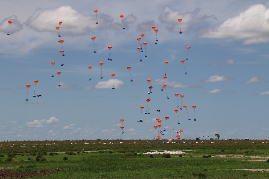
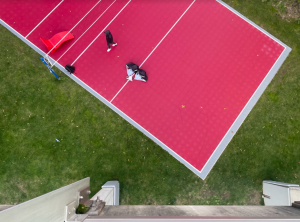
This week, we dropped our device with motors for the first time to test the propulsion. Here is the video: Drop Test.

We found that A. the unsynchronized drop caused a spin in the device and B. the parachute set up created even more spin. Due to how the motors are set up, any small amounts of spin will cause the device to continually spin as the motor fires. To mitigate this risk, we have shortened the parachute slack, and attached the parachutes properly using carabiners with holes in the housing (instead of tape). We must now drop it again to see if this fixes the spin issue. If this does not, we plan to design an arm system that will place the parachutes further from one another in a square formation, with the addition of two more parachutes (which we have ordered)


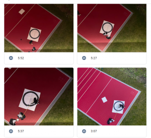
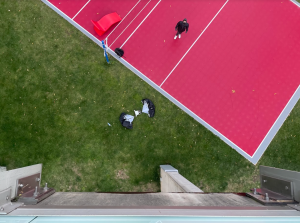
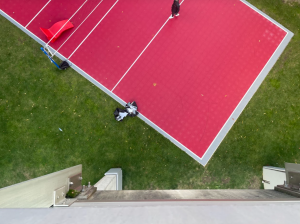
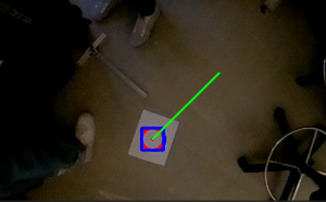
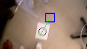
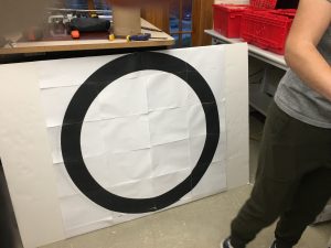
Lastly, as we moved to a CV based approach, we ran the Hough circle detection algorithm on the Pi and found that it is successfully able to detect circles (5 cm radius from a 1 meter height). We plan to print a 0.5 m radius circle and test the detection from the Pausch bridge next (0.5 m radius found from scaling up the 5 cm example to the height of the bridge). According to how well this works, we may need to use a larger circle, or tweak the algorithm by changing some sensitivity parameters.


Team Status Report for 10/9/21

This week the items that we ordered last week arrived. This allowed us to do more pretests, namely the thrust of our propellers and the drop speed of a weight with a parachute. On Thursday we prepared these tests at the lab. First, we filled a tupperware container with water to weigh about 1kg, since this is the expected upper bound for our device weight. We then attached the two 54-inch parachutes to the container and secured it with the duct tape. 

We walked these items over the Pausch Bridge, and tossed them off, while one of us recorded a video of the drop from a distance. The video indicates a time from release to landing of about 3.8 seconds. This is approximately the amount of time during which the device can operate, and it is very close to the amount of time we anticipated. Video

Meanwhile, we also began creating an apparatus to measure the thrust of the motors and propellers. The apparatus consists mainly of a motor and propeller mounted to some wood, placed on a scale, with a battery and PWM generator. An image of the full setup is attached below. With the propeller at full speed, the change in weight indicated by the scale provided us with a verifiable measurement of the thrust: 400g. Our test was not ideal, and it appears that some of the thrust was exerted onto the scale, because the arm may have acted as a moment arm. To remain on schedule we are accepting these results and moving on. As a form of early risk mitigation, we are researching thermal cameras as an alternative to antennas.

Team Status Report for 10/2/21

This week we prepared our design presentation and continued to order parts. Our design presentation consists of much of the introductory information from the proposal, with a few updates. For example, we updated the schedule to be more detailed because we had a better idea of our tasks. We created a block diagram based on the parts we ordered and our integration plan. 

We researched and ordered more parts earlier this week including a 4-pack of motors, 16-pack of propellers, 4 ESC controllers, bullet connectors, and a 2-pack of parachutes. This makes up a bulk of materials, not including a housing unit to put them inside of. We received the Wi-Fi board and after some delay, we finally received the antenna we ordered last week. We ran some pretests on the antenna and board and determined the directional antenna was usable for direction finding. A problem we saw with the RSSI data we collected was considerable noise. We plan to use a filter to remove it, so we will research RSSI filter design in the coming week.

Because of the delay on the antenna and a few other parts we are still waiting on, we have adjusted the schedule. Our pretest phase will continue into the week of design presentations. We hope to verify some important metrics during this time, namely, drop speed with the parachute and thrust of the propellers.

An updated schedule and CAD model is attached.

Team Status Report for 9/25/21

This week we researched directional antennas and accompanying boards. We were looking for antennas that were small enough that could fit on our device and strong enough directionality for our purposes. We looked at EE forums to find one that would suit our use case. We then searched for these products on Amazon. We considered multiple approaches on how to get the RSSI. One idea was multiplexing between antennas, but this might result in higher latency. We arrived on individual ESP32 based boards, one per antenna, these act like Arduinos so we can get RSSI from existing libraries.

With the single computational unit, RSSI retrieval of the several directional antennas will happen sequentially. So a risk that we have discussed at this stage is latency when computing RSSI. Our risk mitigation plan for this issue is to implement a multithreading system or  reduce the number of antennas.

No design changes or schedule changes so far.  We are on track, contingent on the materials we ordered working for our project.


Team Status Report for 9/18/2021

As of today, we finalized our proposal for the presentation next week. This involved several kinematic models which we created earlier in the semester to better quantify our requirements.

One of the most significant risks we predict for our project is its ability to perceive the target and activate propulsion with minimal latency. We anticipate that the system will need some time for movement in between perception tasks (receiving and processing a signal from the target). The device may not move fast enough if the perception tasks are to close in time. We will manage this risk as we write the software for these perception tasks. This pause will be something to take into account when programming the device. We will also make sure directional antenna signal processing will require a small compute time. Our contingency plan would be to switch our perception method to computer vision, to detect visual markers on the ground.

No design changes or schedule changes have occurred yet.

Below is a drawing of our preliminary design: