Oct 10-16:
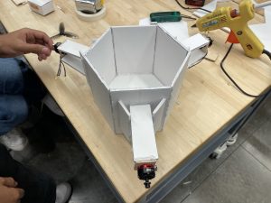
This week, we worked on creating out first prototype as a way to test our propulsion, then our perception after we determine our propulsion works. We chose foam-core as our material so we could rapidly prototype for cheap. Below is the completed housing with the motors attached:

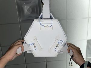
We then needed to run the motors. At first, we tried a Raspberry Pi to generate the necessary PWM signal; however, we found that the Raspberry Pi only has 3.3V logic, whereas the ESC required 5V. We moved to an Arduino Uno for the meantime as it has 5V logic, but are planning to use logic-level converters to step up to 5V. We also decided that for testing purposes, we should have a start and stop mechanism. For starting, we used a single button that once pressed, started the device after 30 seconds. For stopping, Vikram suggested 3 buttons on the bottom of the device that stop the device once pressed under its own weight. The device looked like this:


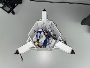
After this was done, we put all the electronics inside and were ready to test the motors. Since it was raining, we had to test the thrust indoors first, so we tied string to the device as one of us stood on a ladder. We found that the motor at 100% had power to move the device (total weight 1.4 pounds. without payload). Here is the link to the video: Motor Test
At this stage, we also received a new ESP32 Board that we could directly connect an external Antenna to without any soldering. This way, we could actually test the performance of the directional antenna and decide if it is usable. We found multiple issues with the antenna approach:
- The antenna had two discernable peaks at the edges of the 30 degree beam width, such that you could not discern from the RSSI if you were to the left or right of the antenna (RSSIs were equal at these two points).
- The middle of the beam width had a trough in RSSI, such that the RSSI read right in front of the antenna, was the same as the RSSI read outside the 30 degree beam width.
- The back of the Antenna resulted in a peak in RSSI similar to being in front of it.
- The Antenna was only able to get reception up to a range of 20 feet. Our drop height is in the range of 30-40 feet, meaning that for the first half of the drop, the perception system would not perceive much.
- The vertical sensitivity of the antenna was very low, meaning as the signal source moves with respect to its vertical position, RSSI changes only towards the very middle of the sweep. This is crucial as the device will be falling downwards.
To mitigate this, we have decided to move forward with a CV based approach using a camera, and a circular visual market.
Oct 17-23:
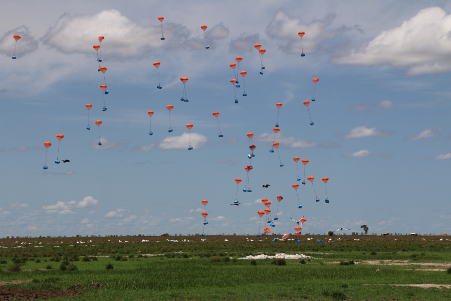
This week, we dropped our device with motors for the first time to test the propulsion. Here is the video: Drop Test.
We found that A. the unsynchronized drop caused a spin in the device and B. the parachute set up created even more spin. Due to how the motors are set up, any small amounts of spin will cause the device to continually spin as the motor fires. To mitigate this risk, we have shortened the parachute slack, and attached the parachutes properly using carabiners with holes in the housing (instead of tape). We must now drop it again to see if this fixes the spin issue. If this does not, we plan to design an arm system that will place the parachutes further from one another in a square formation, with the addition of two more parachutes (which we have ordered)
Lastly, as we moved to a CV based approach, we ran the Hough circle detection algorithm on the Pi and found that it is successfully able to detect circles (5 cm radius from a 1 meter height). We plan to print a 0.5 m radius circle and test the detection from the Pausch bridge next (0.5 m radius found from scaling up the 5 cm example to the height of the bridge). According to how well this works, we may need to use a larger circle, or tweak the algorithm by changing some sensitivity parameters.
