Team Status Report for 11/20/21

This week we wanted to test the propulsion fixes we worked on last week, since we got the chance to charge the battery fully. With the weights also redistributed and the thrust at 75% we were able to produce some movement. It was particularly windless that day, so the motor off drop is directly below the dropping point.

Pictured: Drop with motor off, 50% thrust, 75% thrust

On Monday we did a camera test to rule out the fisheye Raspberry Pi camera against a equirectangular Logitech camera. The camera is a bit heavier but the detection is a lot better that the Pi camera. Once we chosen the Webcam, we also varied the the resolution to see the tradeoff between detection rate and fps. With 480p we had 62% and 3.9fps with 720p we had 46% and 1.7fps. We will likely repeat this test, because the change in lighting between trials was substantial which is why the detection rate is not higher like expected, but the frame rate is clearly to low with 720p. Any smaller resolutions compromise detection and larger ones compromise frame rate.

The rest of the week we spent planning and fabricating the new device housing. We made several CAD models, laser cut most of the body, but were unable to 3D print because of time. We will be 3D printing the arms on which the propellers attach, and this will be a priority next week.

Lahari’s Status Report for 11/20/21

This week in class we tweaked the computer vision and worked through our propulsion issues. The later part of the week we finalized the design for the robot and did some fabrication. On Monday, we went out to test the propulsion with the fully charged battery added thrust. These changes seemed to make all the difference and our device was able to move a sizeable distance based on the photos attached. There was a some mid-air rotation so this will be the focus going into next week.

We also did a test to compare the Raspberry Pi (fisheye) camera and the Logitech webcam to see which was better for detection at different lateral distances. With the large circle (2-meter diameter) I printed this week, there was 0% detection with the Pi camera and about 60% detection on the Webcam on average. We will be moving forward with the webcam. We also tested detection rates and frame rate against resolution and found 480p to be optimal.

From Thursday onwards we made CAD models and fabricated the final design in TechSpark. Vikram made the designs for the walls and base of the device, while I designed the lid and added some hardware cutouts using SolidWorks. We decided to use Acrylic, which I laser cut on Saturday.


Vikram’s Status Report 11/20/2021

This week I worked on the CAD models for the updated housing. We also did tests with the camera at the bridge to the performance of different cameras.

The new CAD model has the frame of the device being made out of laser cut 1/8 inch acrylic, and the arms made out of 3d printed material. We were able to cut 5 of the 6 new walls and bottom plate. Access to 3D printers has been difficult, so the new arms have not been printed yet.  The updated housing will use brackets internally to keep rigidity, as well as a hinge on the top for ease of opening/closing.

For the camera tests,  we found that the fisheye lens just wasn’t conducive to detection because it shrunk everything close to the center, making even large circle detection markers impossible to make out over video. We have switched to a larger target, and a webcam which has much better performance at distance. In addition to a straight up vertical test, we also tested the performance/detection range of the webcam horizontally, testing 3 different lateral distances from the marker, as well as 3 different resolutions.

Next, I would like to measure the latency of our system to see responsiveness to different commands. This will help us gather more data, in addition to the drops we conducted (and will conduct).
The trade studies for the camera are ongoing and for the propulsion system we hope to characterize different proportional thrust values, as well as just using constant thrust vectors.

Daniel’s Status Report for 11/20/2021

This week, I helped the team do more tests in order to see if we could replicate the results we found last week regarding our solution of the swinging problem. We also finalized our choice of cameras after some range tests off the bridge, and began designing our final housing.

For the drop tests, we first lowered the total added weight through rocks to exactly 1 pound (it was 600g before, whereas ~450g/1lb is the actual weight of our payload). We also charged the battery fully and ran additional thrust tests using the scale. We found that at 100% power using 16 AWG wure, we were getting almost 700g of thrust, a marked improvement over previous week’s results.

For the actual drops, as usual, I held up the device by the parachutes as Lahari initiated the device. We first ran with 50% power to the motors and noticed a very minute movement. We then decided to change this to 75% and dropped an additional two times, noticing noticeable levels of movement in the direction of the motors. I also took pictures from the bridge looking down to document where the device landed, so we could compare to the no motor drop.

To try alternative cameras, I ordered an 120 degree camera from the ECE parts inventory to see if the smaller FOV would make the circle easier to detect. I tried setting it up with the Pi only to find that the one we had was for the Nvidia Jetson, so the Firmware was not compatible. I then helped Lahari and Vikram modify existing scripts we had in order to support a USB webcam (as the exiting PiCamera module only supported the CSI Pi Camera module). This involved modifying the code to use the generic OpenCV camera access functions, rather than PiCamera specific methods. After this was done, we went out to test this new webcam against the old 160 degree FOV camera.


We came up with a quick testing strategy where I would hold the device over the bridge, say the testing parameters out loud (resolution + camera type + lateral distance from target), and Lahari would record the screen and mic feed using OBS. Using a tape measure, I measured up to 4 meters away from the location of the target, with increments of 1 meter such that we measure the performance of each camera at each resolution at each distance away from the target center. Lahari and I started with the 160 FOV fish eye camera and noticed that it was not even picking up the target on the ground, even after we doubled its diameter to 2 meters (the fish eye effect made everything in the center of the frame super small). We decided to call of the further tests with the fisheye, and moved onto the Webcam. With the Webcam, the target was large and clear in the frame, and we were able to proceed with the entire suite of tests. (640 x 480 vs 1280 x 720, at 1, 2, 3 and 4 meters away from the center of the target).

Lastly, we brainstormed ideas together for a final housing. As we ended up choosing acrylic, Lahari and I worked together to quickly create DXF files for the hexagonal base of the device, as well as the rectangular side walls using Solidworks. Our next phase is to fully construct this housing, and test the device with the full camera to propulsion piepline.

Daniel’s Status Report for 11/13/2021

This week, I helped the team prepare for and present our demo to the two groups on Monday and Wednesday, as well as work on modifications to the device to solve swinging problems in the air.

On Sunday before the demo, we worked together to fine tune the demo setup by testing what thrust to use, and how high up to tie the device to appropriately show off our system. Additionally, we ran various tests to see if the system performed as expected, as Vikram and I moved the circle under the device, and Lahari modified the detection code accordingly to improve detection. For the demo itself , I gave a brief overview of the main components of our project, then explained specifically my part (the vectorization algorithm), and how it fits into the overall data pipeline (my algorithm receives data from the CV subsystem, and passes it onto the arduino via UART).


After the demos, due to the low thrust we measured for each of our motors using the smaller props (~220g), I researched various thrust tests to see what other people were getting. I noticed people were getting easily over 800g using our motor with a 4S LiPo and 5 inch props (like us), so I suggested to the team that we should construct a proper motor thrust setup (motor attached to a raised platform, with a flipped propeller to generate thrust downwards onto a scale. Lahari and I found a wooden rod, and with the help of a friend, cut it to an appropriate size. I then measured the middle of a rectangular platform and glued the rod to it to give it a solid base. We then attached the motor to the top, and ran several tests. We found 330g of thrust with the 3S LiPo (the 4S was low battery), and 400g using thicker wires for the ESCs.

In order to solve the swinging problem we noticed in the air (which we attributed to lightness), we thought it would be beneficial to add weight to the device. I suggested we could use fish aquarium rocks (which I knew Lahari may have) as a stand in for the payload. We measured three 200g  bags of rocks, and Lahari and I cut a hexagonal insert such that we could put the bags at the bottom of the device, and cover them with this platform. After this, we tested  the device off the bridge (I dropped it, Lahari initiated it and Vikram caught it) and noticed the swinging no longer occurred, but minimal to no movement was observed. We then found that the 4S LiPo was low battery, causing the motors to slow down mid flight, so we charged it. Our next tests will have a fully charged battery, and 2 instead of 3 rock bags; we will then change thrust and weight accordingly to what we observed.


I also helped the team run detection tests for the circle off the Pausch bridge. I held the device off the side as Lahari viewed the camera feed on the laptop and made on the fly edits to the detection code. We found that the circle was too small to be detected in the thresh-holded image, so we printed a circle two times the size (2 meter diameter), and will be testing with that as soon as we construct it.


Lastly, I researched and ordered larger propellers (7 inches) in order to increase thrust further, incase we still cannot move after lowering the weight and using a fully charged battery.

Vikram’s Status Report for 11/13/2021

This week, after we demo’d I went to work on improvements to our physical drop system. First, I wanted to explore whether we were getting peak thrust from our motors by using a higher-gauge wire from the controllers to the motors. This change yielded a gain of 70g of thrust per motor, which was not insignificant. We will be moving all of our connectors to this 16AWG wire. Additionally we ordered 7 inch propellers that fit our shaft diameter, which are a 1 inch step up from our current props. I also measured our battery voltage and realized that it needed to be charged because on some of our pre-drop tests, the motors were struggling to keep thrust. I hope with topped off batteries, larger propellers, and thicker wires we will be able to push the most thrust possible out of our motors.
We also did a drop with the added weight to try and reduce swinging. This succeeded, but the added mass was a bit much, and we didn’t swing but we also didn’t move very much laterally. I think that using a solution in-between, where we decrease the added weight slightly, and use the aforementioned thrust changes will help balance the variables so that purposeful movement is possible.

Additionally, we went to the bridge again to test our perception system, where we found that the camera lens was working against us, and the fisheye made it hard to see the circle at the bottom with our processing added on. Using a standard camera or different lens should help to alleviate this, especially because the ultra wide fisheye is overkill when dropping from such height.

Lahari’s Status Report for 11/13/21

This week we focused on our propulsion system as a team. We added weights to the inside of the device, to combat the swinging problems we faced before. The weights were successful in removing swing, but the insufficient lateral movement from our propellers was still a problem. Vikram suggested that the problem was that the connectors between the ESC and the motors were too thin to handle the current. While he made new connectors, Daniel and I created a new thrust testing apparatus at TechSpark. We went for a new design that we saw online, consisting of a pillar, with the propeller at the top. This would allow airflow which is important, so the propulsion is not impeded. We were able to generate 70 grams more with the thicker wires.

Since the camera to motion pipeline seemed to work in the demo setup, it was important that we also tested the CV in the actual testing setting. So we headed to the Pausch bridge to see the camera feed and detection. We tried to change the thresholds and parameters around, but found that the 1m target we have was miniscule because of the fisheye lens. The fisheye lens does not seem optimal for our use case namely, it distorts shapes the further they are from the center of the frame and downsizes shapes that closer to the center. It likely that a equirectangular camera will work just fine for our project, because the field of view from 43′ height can easily cover a 3 meter radius. Keeping with the fisheye lens, we could try a software algorithm to correct fisheye to equirectangular. Or more simply, we could enlarge the center of the frame, discarding data on the edges of the frame, because this is the only data we are concerned with. A backup plan is to use a USB webcam.

Team Status Report for 11/13/21

This week we finished up the interim demo and continued testing to improve the propulsion system and computer vision. At the end of last week, we finished integrating the Raspberry Pi with the Arduino in the prototype we have been working with. On Sunday we finished the integration phase by calibrating our software to respond to a circle target placed below the device (where the camera is pointed). We found that the camera feed was off center. That is, the center of the frame was not exactly directly below the camera. This would have been an issue later because when the target is near the frame’s center, we want to fully deactivate the motors. Another issue was that we had to assign one of the motor directions as the origin, or 0° point. As it was, the direction derived from the computer vision was not synced to the direction of the motors. To correct for both of these problems we added an offset of about 30° to the angle and 200px to the center inside the circle detection script. 

After the demos were completed we prioritized working on our propulsion thrust because it was not enough to get our device moving enough. We fabricated another thrust testing apparatus to measure the amount of thrust being produced. 

The propulsion is exerted down onto the scale and originally measured 330 grams. We theorized that the low gauge of our wires was inhibiting current from the ESC to the motors. When we replaced these connectors with thicker ones, the thrust was 400 grams. Another measure we took was adding 600 grams of gravel to the inside of the device, as a weight. This was meant to increase the tension in the parachute straps, to reduce swinging. We did a drop test with this setup and the swing was reduced, but our propulsion was still insufficient. We found after returning to the lab that the battery was low on charge. We will be trying again with increased propulsion tomorrow, weather permitting. 

Thrust test with low vs high gauge wires:

Lastly, we held the camera over the Pausch bridge to see if our detection would work after all the changes we made over the past two weeks. This week, we reduced the shutter speed to reduce motion blur. This change increased the detection rate from about 35% to about 90% in the indoor setup. We found that the circle was too small in the camera feed when held from the 43’ height. We are working on two avenues to fix this. One is to print a 2-meter circle instead of the 1-meter target we have now. The other method is to enlarge the usable portion of the fisheye image or correct it to be equirectangular. Our mitigation strategy for this area is also to start testing on a USB webcam, which will altogether remove the issues we face with a fisheye lens, but add more weight. 

Note the lack of motion blur with the faster shutter speed, both frames taken mid-swing:

1500 microsecond exposure time

9995 microsecond exposure time (circle is not detected!)

Lahari’s Status Report for 11/6/21

This week I improved my CV  target detection code and helped the group with more drop tests and some integration tasks. For integration we finally combined the propulsion system inside the housing with the PWM generation code that Daniel prepared and the CV code that I worked on. Daniel and I built an apparatus, pictured in the team report, to hang the device from for our demo. I uploaded my code to the Raspberry Pi, and adjusted it to the new camera. The fish eye lens was different from that of my laptop camera so I had to reduce the perfectness parameter and increase the maximum radius from 30 to 50 pixels to make it visible at the distance fit for our use case.

The earlier part of the week I spent making my CV more robust. I did a number of things to address problems like false circles and misattribution of the target. These changes have made the algorithm more robust, and affected the latency minimally. We measured about 6fps before and 5fps after.

  1. I performed HoughCircles on a thresholded image instead of the original grayscale image. This means the image was changed to binary, with pixel values above a certain value turned to 255, and the rest to 0. Our target is black against white, so circles where the gradient is less will not be present in the thresholded image.
  2. When the circle is lost, most likely due to motion blur, the last known location of the target is stored.
  3. When there are multiple circles, we choose the one whose center is the least Euclidean distance from where the target was last found.

Daniel’s Status Report for 11/6/2021

This week, I worked primarily on helping the team test the device with more drops, as well as implementing the vectorization algorithm, and integrating it with the arduino code (which controls the motors) and the CV code (which detects the circles). We then worked as a team to test the full detection-to-propulsion pipeline.


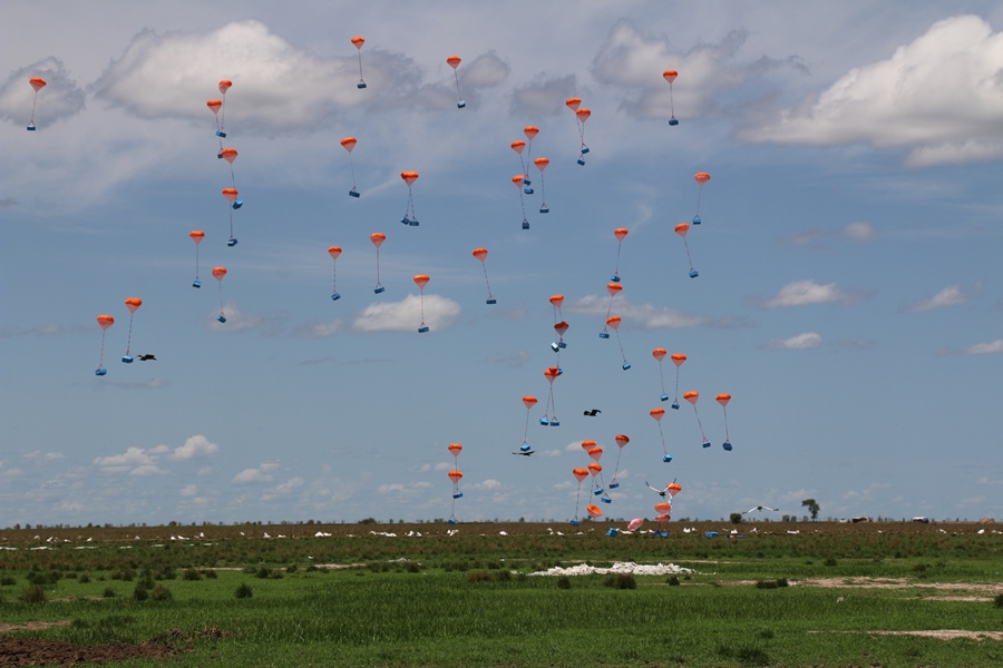
For the drops, we tried various parachute setups (2 vs 3, shorter and longer slack lengths). As usual, I held up the parachutes and let go of the device as Lahari initiated it with the press of a button and Vikram was below to catch it. We noticed a pendulum motion as I dropped the device. We then tried to drop the device, then initiate the motors mid flight, but the same issue persisted. We think this may be a lightness issue, so we will resume drops after the interim demo with additional weight at the base of the device to prevent swinging.

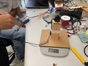
As for the vectorization code, I implemented it in Python, and sent the data over serial so the Arduino can use the values. In short, the algorithm takes in the angle and magnitude of the vector towards the target, from the center of the frame, and computes the necessary PWMs for each of the three motors that will create a resultant vector that is equal to the target vector. After this, we tested the script by connecting the Arduino (which was running code Vikram wrote to receive the PWM values over serial), and noticed a hanging/slowdown using the serial over the USB connection. We then moved to the GPIO RX and TX pins, and using a logic-level-shifter, connected the Arduino and Pi directly. This solved the hanging issue (the serial over USB is prone to slowdowns as it is dependent on the processor frequency). Then, I helped the team test the vectorization algorithm by inputting various angles to the script, and seeing if the correct motors spun up. Since our motors are defined at angles 0, 120 and 240 degrees, we tried these values as well as values in between (such as 60 and 90), and found that it worked as intended, meaning I was on schedule with its completion.


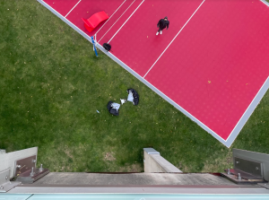
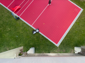
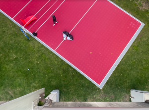
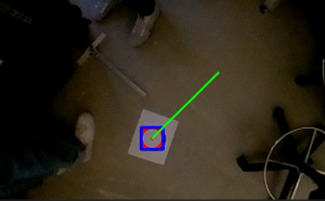
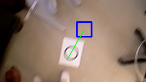
After this, I then worked to integrated the full Camera to Propulsion pipeline by having the CV Python script call the Vectorization algorithm, which then communicates with the Pi over serial. To test this, I placed a circle on the ground as the target and moved it around, checking to see if the angle generated by the CV code was being passed on to the vectorization algorithm, then seeing if the correct motors spun up. With some CV tuning, we were able to get a consistent detection-to-propulsion pipeline, as the circle changes position the motors move accordingly; however, one issue we found that we will fix tomorrow is the relative angle 0 to the camera, and to the device were not matching. This meant that an offset existed between the angles that the device moves towards, and the angle the camera produces . This should be a matter of experimentally deducing which angle is 0 to the camera, which angle is 0 for the device, and matching those. The above was all tested using our new demo setup (described below), as I ran the camera+vectorization script on the Pi and Vikram and Lahari turned the device on or off between tests.

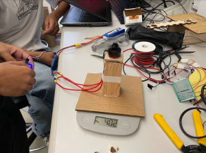
I also helped the team build a testing setup to demo our device for the interim demo on Monday. This involved getting various 80-20 pieces and attaching them in such a way that would allow us to hang the device over a target using string. We tested the setup and found that it was able to hold the device stable, as well as allow it to move a sufficient amount to demonstrate the mobility of the system.