Team Status Report for 12/4/21

Over the past week we have been working on the two pending tasks on the schedule: final testing and housing. We laser cut the remainder of the pieces and attached them to the 3d printed arms and brackets we made before the break. The body is pretty sturdy and awaiting drop testing, but as a form of risk mitigation we still have our prototype. The new housing unit is completed (video) so the only other task in our schedule is to finish up testing. In today’s round of testing we had four trials:

Min: 1.27 m

Max: 2.84 m

Mean: 2.40 m

Median: 2.74

We have been making adjustments to the code as we go with our trials, like adjusting binary threshold and thrust from trial to trial. We have also been able to reduce the latency by removing a delay in the function that sends data to the Arduino via serial. The movement is much smoother after we made this change. Our goal for the next week to finish drop tests by Tuesday so we can switch focus to shooting our video and working on the final report.

Lahari’s Status Report for 12/4/21

Over the past two weeks we continued to work on the final housing unit and did more drop tests. I laser cut the remainder of the pieces including the lid, and a few more of the wall pieces. I fully assembled the housing over the last few days, then we glued everything into place. Vikram and I soldered some new connectors for the new housing and we mounted a new set of motors to the arms. We plan to showcase this product instead of the prototype at the demos and in our video. We have been working on final testing as well over the last few weeks.

Before the presentation  we did several tests pertaining to our design choices. Namely, we collected data for tradeoffs related to camera lens, camera resolution, battery cell count, and propeller size. I redid the test of camera resolution against detection rate and frame rate as the results we had from the week previous were done under varying light conditions, the new results showed a more clear tradeoff between frame rate and detection rate. Since the presentation we have been working on final drop tests as we were unable to get enough trials in before the presentation. We completed 4 trials of drop testing today. The closest landing distance was around 1.25 meters. We have found testing to be pretty feasible at night as well, with a lower threshold value since the light from the bridge illuminates the target.

Team Status Report for 11/20/21

This week we wanted to test the propulsion fixes we worked on last week, since we got the chance to charge the battery fully. With the weights also redistributed and the thrust at 75% we were able to produce some movement. It was particularly windless that day, so the motor off drop is directly below the dropping point.

Pictured: Drop with motor off, 50% thrust, 75% thrust

On Monday we did a camera test to rule out the fisheye Raspberry Pi camera against a equirectangular Logitech camera. The camera is a bit heavier but the detection is a lot better that the Pi camera. Once we chosen the Webcam, we also varied the the resolution to see the tradeoff between detection rate and fps. With 480p we had 62% and 3.9fps with 720p we had 46% and 1.7fps. We will likely repeat this test, because the change in lighting between trials was substantial which is why the detection rate is not higher like expected, but the frame rate is clearly to low with 720p. Any smaller resolutions compromise detection and larger ones compromise frame rate.

The rest of the week we spent planning and fabricating the new device housing. We made several CAD models, laser cut most of the body, but were unable to 3D print because of time. We will be 3D printing the arms on which the propellers attach, and this will be a priority next week.

Lahari’s Status Report for 11/20/21

This week in class we tweaked the computer vision and worked through our propulsion issues. The later part of the week we finalized the design for the robot and did some fabrication. On Monday, we went out to test the propulsion with the fully charged battery added thrust. These changes seemed to make all the difference and our device was able to move a sizeable distance based on the photos attached. There was a some mid-air rotation so this will be the focus going into next week.

We also did a test to compare the Raspberry Pi (fisheye) camera and the Logitech webcam to see which was better for detection at different lateral distances. With the large circle (2-meter diameter) I printed this week, there was 0% detection with the Pi camera and about 60% detection on the Webcam on average. We will be moving forward with the webcam. We also tested detection rates and frame rate against resolution and found 480p to be optimal.

From Thursday onwards we made CAD models and fabricated the final design in TechSpark. Vikram made the designs for the walls and base of the device, while I designed the lid and added some hardware cutouts using SolidWorks. We decided to use Acrylic, which I laser cut on Saturday.


Lahari’s Status Report for 11/13/21

This week we focused on our propulsion system as a team. We added weights to the inside of the device, to combat the swinging problems we faced before. The weights were successful in removing swing, but the insufficient lateral movement from our propellers was still a problem. Vikram suggested that the problem was that the connectors between the ESC and the motors were too thin to handle the current. While he made new connectors, Daniel and I created a new thrust testing apparatus at TechSpark. We went for a new design that we saw online, consisting of a pillar, with the propeller at the top. This would allow airflow which is important, so the propulsion is not impeded. We were able to generate 70 grams more with the thicker wires.

Since the camera to motion pipeline seemed to work in the demo setup, it was important that we also tested the CV in the actual testing setting. So we headed to the Pausch bridge to see the camera feed and detection. We tried to change the thresholds and parameters around, but found that the 1m target we have was miniscule because of the fisheye lens. The fisheye lens does not seem optimal for our use case namely, it distorts shapes the further they are from the center of the frame and downsizes shapes that closer to the center. It likely that a equirectangular camera will work just fine for our project, because the field of view from 43′ height can easily cover a 3 meter radius. Keeping with the fisheye lens, we could try a software algorithm to correct fisheye to equirectangular. Or more simply, we could enlarge the center of the frame, discarding data on the edges of the frame, because this is the only data we are concerned with. A backup plan is to use a USB webcam.

Team Status Report for 11/13/21

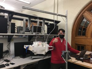
This week we finished up the interim demo and continued testing to improve the propulsion system and computer vision. At the end of last week, we finished integrating the Raspberry Pi with the Arduino in the prototype we have been working with. On Sunday we finished the integration phase by calibrating our software to respond to a circle target placed below the device (where the camera is pointed). We found that the camera feed was off center. That is, the center of the frame was not exactly directly below the camera. This would have been an issue later because when the target is near the frame’s center, we want to fully deactivate the motors. Another issue was that we had to assign one of the motor directions as the origin, or 0° point. As it was, the direction derived from the computer vision was not synced to the direction of the motors. To correct for both of these problems we added an offset of about 30° to the angle and 200px to the center inside the circle detection script. 

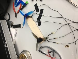
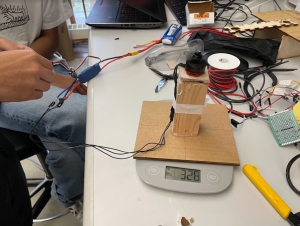
After the demos were completed we prioritized working on our propulsion thrust because it was not enough to get our device moving enough. We fabricated another thrust testing apparatus to measure the amount of thrust being produced. 

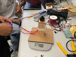
The propulsion is exerted down onto the scale and originally measured 330 grams. We theorized that the low gauge of our wires was inhibiting current from the ESC to the motors. When we replaced these connectors with thicker ones, the thrust was 400 grams. Another measure we took was adding 600 grams of gravel to the inside of the device, as a weight. This was meant to increase the tension in the parachute straps, to reduce swinging. We did a drop test with this setup and the swing was reduced, but our propulsion was still insufficient. We found after returning to the lab that the battery was low on charge. We will be trying again with increased propulsion tomorrow, weather permitting. 

Thrust test with low vs high gauge wires:

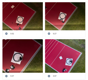
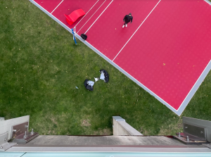
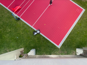
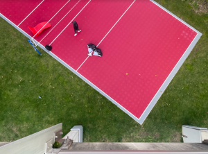
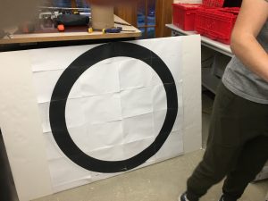
Lastly, we held the camera over the Pausch bridge to see if our detection would work after all the changes we made over the past two weeks. This week, we reduced the shutter speed to reduce motion blur. This change increased the detection rate from about 35% to about 90% in the indoor setup. We found that the circle was too small in the camera feed when held from the 43’ height. We are working on two avenues to fix this. One is to print a 2-meter circle instead of the 1-meter target we have now. The other method is to enlarge the usable portion of the fisheye image or correct it to be equirectangular. Our mitigation strategy for this area is also to start testing on a USB webcam, which will altogether remove the issues we face with a fisheye lens, but add more weight. 

Note the lack of motion blur with the faster shutter speed, both frames taken mid-swing:

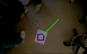
1500 microsecond exposure time

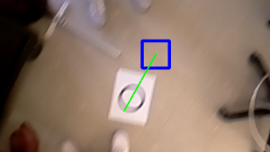
9995 microsecond exposure time (circle is not detected!)

Lahari’s Status Report for 11/6/21

This week I improved my CV  target detection code and helped the group with more drop tests and some integration tasks. For integration we finally combined the propulsion system inside the housing with the PWM generation code that Daniel prepared and the CV code that I worked on. Daniel and I built an apparatus, pictured in the team report, to hang the device from for our demo. I uploaded my code to the Raspberry Pi, and adjusted it to the new camera. The fish eye lens was different from that of my laptop camera so I had to reduce the perfectness parameter and increase the maximum radius from 30 to 50 pixels to make it visible at the distance fit for our use case.

The earlier part of the week I spent making my CV more robust. I did a number of things to address problems like false circles and misattribution of the target. These changes have made the algorithm more robust, and affected the latency minimally. We measured about 6fps before and 5fps after.

  1. I performed HoughCircles on a thresholded image instead of the original grayscale image. This means the image was changed to binary, with pixel values above a certain value turned to 255, and the rest to 0. Our target is black against white, so circles where the gradient is less will not be present in the thresholded image.
  2. When the circle is lost, most likely due to motion blur, the last known location of the target is stored.
  3. When there are multiple circles, we choose the one whose center is the least Euclidean distance from where the target was last found.

Team Status Report for 11/6/21

This week, we completed several more drop tests and prepared the interim demo for next week. We inferred from last week’s tests that there was not enough thrust to move the 3 meters that we wanted. Our idea then was to use two motors on each of the three sides instead, to hopefully double the thrust. At a TA’s suggestion, we also acquired larger propellers as another way of increasing the thrust. The thrust tests, done on a scale, showed 600 grams with double propellers. It was approximately 600 grams with the large propellers as well, but these were not meant for the motors we had so they couldn’t be installed properly without vibration.

We did a few drop tests on the double propeller arrangement we put together last week. We repeated the tests several times, each time adjusting for different variables. The first time around, we noticed there was swing so we changed the Arduino code to start after the drop began. On later tests we had to address spin and lack of movement. We were unable to modify the design so that the propulsion system would move where we wanted. This is the area of our project that is the most uncertain at this point. To mitigate risk, the next time we get the chance to do a drop test we want to add balanced weights to the inside of the device. We think that a persisting problem is the lack of tension between the parachutes and the device. With this change movement will not be impeded by swing or spinning. Video

For our interim demo, we set up an apparatus that will suspend our device 1.3 meters off the ground, while we move around a target image of 10cm diameter below the camera on the bottom. This models our actual 13 meter drop height against a 1 meter target diameter. We will show that we can activate the propellers in the correct direction based on the target’s relative location.

Lahari’s Status Report for 10/30/21

This week we had several tests to carry out. The first was a drop test, which we did again at the Pausch Bridge. This test would tell us whether we had eliminated spin by adjusting the parachutes, and the amount of thrust in our propellers. Last week, I made a few design changes to avoid the spinning that was happening during the drop. I shortened the straps of the parachute and attached them to the body with carabiners. In testing this proved successful by eliminating spin during the fall.  A picture of the parachute attachment now:

Initially, I tested the circle detection CV using a small image of a circle. Adjusting the parameters of the script, I found a range and line thickness of a circle that would make it visible. I scaled this up linearly to estimate we need a target diameter of at least 1 meter with 10cm thickness. I then printed the 1 meter circle piecewise on several letter size papers and stuck them to a board (pictured in team status report). We tested the large circle and found it was detected at a range fit to our use case, i.e. it was detectable close up and from 43 feet away (the height of the Pausch Bridge).

Team Status Report for 10/30/21

This week we improved on the drop test from last week, the problem was that the device spun during most of the descent and the parachute ropes twisted together. To fix this, we shortened the ropes and mounted them on opposite sides of the top. This solution would ensure that the parachutes were separated during the whole drop. Spinning would otherwise interfere with our perception method, which ultimately determines the relative angular position between the device and the target. When we tested this version on Monday there was no noticeable spinning. 

We then shifted our focus on movement from our propulsion system. We wanted to see how far the propeller at full thrust would move the device. Wednesday was more appropriate for the lateral distance test, because it was not windy. By this time, another set of parachutes had arrived, so we added a third parachute to the body, so the drop time would be longer. The test showed an additional parachute did not achieve this. We would like to test this a few more times before we reject this option, especially because there is more weight that needs to be added, including the payload and extra propulsion. 

At full thrust, the device could not move three meters laterally, a key technical requirement of our project. We decided that each arm of our device should have two propellers instead  of one. We already had an extra motor, ESC, and propellers, so we put double propellers on one of the arms. We plan to test the new thrust capability on Monday, and decide whether to order more parts.

Meanwhile, we conducted a few tests on the circle detection code. We found the 1m diameter circle (pictured below) was detected between 48 feet and 10 feet of distance. It is approximately the same indoors and outdoors. We plan to find the angular range of detection at a few fixed distances next week.