Accomplishment
- Ethics (4h)
- CAD designs(8h)
- Turns Switch Cad V1
- Led Cad V1
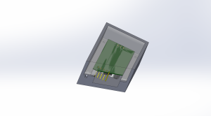
- Pi V1
Schedule
- CAD (Partial Finish, still need battery)
Next Week Plan
- Battery Cad
- Refine all Cad
- Turn switch electrical section
Document

Switch Cad V1
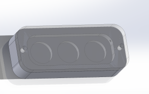
Led Cad V1
Carnegie Mellon ECE Capstone, Spring 2024 – Johnny Tian, Jack Wang, Jason Lu
Accomplishment
Schedule
Next Week Plan
Document

Switch Cad V1

Led Cad V1
Risk and Plans
We are trying to bring more components of the project together. Some current tasks are making sure the software bring-ups are successful, and that hardware design will fulfill our needs. One of the risks that might jeopardize our progress would be running into issues that we did not expect. For example, the radar software bring-up took a bit longer because we had to resolve some basic UART communication issues that were related to the Pi. In addition, we were trying to find optimal materials for our radar cover, which we did not initially believe to be this time-consuming and challenging. However, it turned out there are a lot of details like the permittivity and the thickness that we need to consider. Such unexpected issues might lead to lengthy delays or, even worse, change of plans. We tried to do as extensive research as possible beforehand to minimize such things from happening, but it is unavoidable like any other engineering project. To mitigate this, we still have our built-in slack time in the project timeline, and we try to dynamically adjust the schedule and plan if needed. The adjustment is based on our MVP requirements. We hope to minimize the impact of unexpected errors by staying on top of the game, and making sure we work through other simple, non-technically intense parts of the project efficiently.
Changes in Design
We do not have any design changes since last week.
Schedule Updates
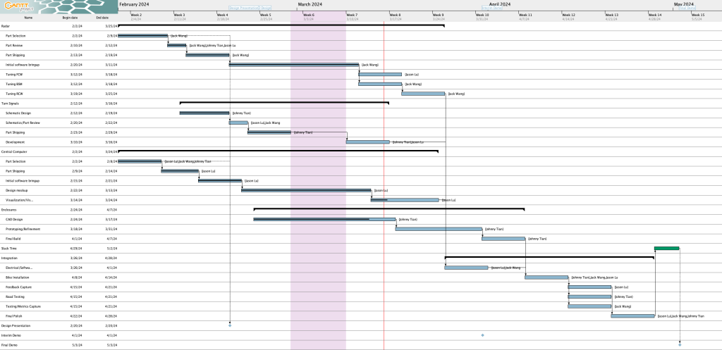
Here is a screenshot of the Gantt chart as of this week:
Here are the schedule updates since last week:
Completed tasks  :
:
On track tasks  :
:
Delayed tasks  :
:
Out of the 4 targets from the last update, I’ve completed 2 tasks (highlighted in green) and 2 tasks are unstarted (highlighted in red).
With respect to the software side of the UI, I am currently on track. However, I am behind with respect to the turn signal control software and radar tuning as both should have been started at this point. I plan to discuss with the rest of the team on the radar timeline as I may not have time this upcoming week to tune the radar.
The main deliverables for this week are:
After last week, I realized that the range indicator for a bicycle which looked similar to a wifi indicator could be ambiguous as to the meaning. For example, if the range indicator is full strength, does that mean the car is near or far?
Therefore, I redesigned the range indicator to be similar to what Toyota has for their parking assist proximity sensing system (see “Distance Display” under this page from the 2021 Venza manual). Under the new system, an arc will light up corresponding to the range of the detected car, with further arcs indicating a longer distance. The color of the arc will also serve as a visual cue, with green indicating far, yellow indicating medium, and red indicating close range.
Other changes this week include:
For comparison, here’s the old design:

And here’s the new design:

From left to right, the screens display:
Future work will include adding a hazard toggling button and perhaps a debug panel or some other way to show debug information.
Here’s the state of the UI at the time of writing:
The icons are exported from Figma, and the flashing turn signals are driven by the turn signal application logic.
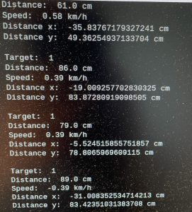
There were some issues in establishing the communication between radar and RPi during the process. Initially, the default UART port for RPi did not transmit nor receive data. This was resolved by updating the firmware of the Pi after reading a post in the forum. After the basic UART functionality was checked out, the radar still was not able to communicate. I realized that the default UART for RPi 4 was a mini-UART, which does not support parity bits based on this chart. 
Our radar requires even parity, so the default UART would not work. I reconfigured the hardware setup so that the radar used UART2, which supports parity bits. This resolved the communication issues. In this phase, I let the radar print out a list of detection targets with their distance and velocity. This concluded the radar’s initial software bring-up task for the project.
I am back on schedule from last week’s slight delay. The initial software bring-up for the radar was completed early this week, and I am in the process of tuning the radar for our needs.
Out of the 2 targets from the last update, I haven’t completed either (highlighted in red):
I am a little behind as I haven’t started on the UI implementation nor completed the UI mockup. I aim to complete the mockup and start the implementation this week.
Therefore, I needed to extend the due date of the mockup from 2/28 to 3/13 (which also pushes the UI implementation start date back), along with changing the UI implementation end date from 3/15 to 3/24 as I’m not confident I can finish it in the original time frame of 1 week (the new allocated time is 1 + 1/2 weeks). This should be OK as I had extra slack time anyways, so there aren’t any delays due to this. There are a lot of tasks going on now so there is a risk of further slippage, but for now this is the plan.
The main deliverables for this week are:
For the UI mockup, I built it using Figma. I’ve heard of Figma but never used it before, but thankfully it seems quite easy to get up and running. Here’s a picture showing mockups of various scenarios:

Note that the UI uses portrait orientation and is inspired in part by Tesla’s visualization (a little bit like the image under “Driving Status” in the Tesla Model Y Owner’s Manual). From left to right, the screens display:
Risk and Plans
Time management is the greatest risk for the current phase of the project. In the past week, the heavy workload caused us to be slightly behind the overall schedule. We are having a slight delay in enclosure design and manufacturing. If we stick with the previous plan, we might be causing massive delays in our project. Hence, while Johnny is speeding up finishing the CAD design, we are also making backup plans of running system integration in parallel with the enclosure design. We are currently running with a reasonable slack time. But if the delay continues, we will run into scheduling problems. We are communicating between team members to make sure that the schedule is updated, and that it is within the tolerances of the slack time that we have. Another challenge is that a design change might add some time to what we have planned. For example, we are learning what kind of materials and specifications can be used for the radar cover as we go through the datasheet, which caused us to take extra time to figure out the new design. These are all managed by cross-checking out plans and splitting the work as needed to make sure that we meet the absolute deadline.
Changes in Design
We have changed our plan for radar radome material. Our current plan is to use closed-cell polyurethane foam to be water-proof while allowing radio waves to pass.
Schedule Updates
There have been some significant changes to the Gantt chart. Here is the updated Gantt chart:

Here is a summary of changes:
Our slack time is now 4 days.
Weekly Special Questions
Note: Part A was written by Jack Wang, Part B was written by Johnny Tian, and Part C was written by Jason.
A. Global Factors:
Our BikeBuddy will have a great impact on the global scale. The system will be able to be installed on different kinds of bicycles, so each individual around the world could benefit from such a system. Bike safety is definitely not only a local concern in Pittsburgh, but an issue faced by all bike commuters around the globe. We try to make the system generic so that it will be able to perform things like blind-spot detection and illuminate turn signals in diverse road and weather conditions. People who utilize it will not need to be technologically savvy. Instead, it will be designed to be able to use and interpret the information easily. This system will not only be beneficial to the cyclist community around the world but to all the general public who shares the road. It will likely reduce the number of crashes between the car and the bike, creating a safer road environment. It will not just be a system that will contribute to those in academics, but a system that people can actually use, benefiting their day-to-day life on a bike, no matter where they are.
B. Cultural Factors:
Integrating blind spot monitoring and turn signaling features represents not only a technological advancement but also an innovation intertwined with cultural factors. In cultures where cycling is popular, these innovations can significantly enhance safety, reflecting a commitment to promoting responsible behavior on the roads and emphasizing cyclists’ well-being.
In diverse linguistic environments where individuals may not share a common language, visual cues become universally understood. Turn signals, as a non-verbal and standardized method of communication enabling drivers and pedestrians to anticipate and respond to upcoming maneuvers.
In addition, clear and consistent signaling enhances adherence to traffic regulations, contributing to a smoother flow of traffic and improved road safety. When riders consistently utilize turn signals, it becomes easier for law enforcement to monitor the traffic.
C. Environmental Factors
If we are able to encourage more people to bicycle instead of taking their car by giving users more confidence in their safety on the road, we can improve the environment by taking more vehicles off the road. This will hopefully improve air quality, reduce use of fossil fuels, and reduce noise pollution.
However, our product itself may have a slight negative environmental impact due to the materials involved in building the system. For example, I believe our battery (Anker 337) uses lithium, and the extraction of lithium can have negative impacts on the environment such as “[the] use [of] large quantities of water and related pollution; potential increase in carbon dioxide emissions; production of large quantities of mineral waste; increased respiratory problems; alteration of the hydrological cycle” (https://news.climate.columbia.edu/2023/01/18/the-paradox-of-lithium/). While our product does not use large amounts of lithium compared to things like electric vehicles or other resources such as rare earth metals that are perhaps needed for things like the Raspberry Pi, we nonetheless do contribute to these issues.
Accomplishment of This Week
Schedule
Plan for Next Week
Documentation
My progress is a bit behind schedule on the radar setup due to the heavy workload for this week. However, I am only a little behind so I will be able to catch up with the schedule by this Monday, without affecting the overall progress of the team. The parameter tunings will start then.
Accomplishment of This Week
Schedule
Plan for Next Week
Documents

1. Presentation (6 hrs): Together with Johnny and Jason, we finished the slide deck for the design review presentation. I made the slides about testing metrics and why we chose to use radar instead of other distance-measuring equipment. During lab meeting time, I listened to other teams’ presentations, asking questions and providing feedback. I was able to hear about other people’s projects while reflecting on our project to see what can we improve in terms of hardware and software design.
2. Miscellaneous (2 hrs): I set up the team GitHub repo for version control. The link to that repo is omitted here since we are not releasing the source code yet. Johnny, Jason, and I did a quick functionality check with the screen that we purchased. I set up the hardware connection between the K-LD7 radar and the Raspberry Pi using a breadboard. This is not the final setup for our system; it is used for software bring-ups and tests that will be discussed in the next section.
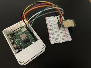
3. Radar Initialization (4 hrs): I began the software bring-up process for the K-LD7 radar. The first phase includes setting up the radar and getting some basic detection results. I did some research on how to get the radar module working with Raspberry Pi and how to get useful output. In the datasheet for K-LD7, I learned the signal processing flow of the module and different parameters such as speed/direction measurement, angle measurement, and distance measurement that we can tune. I discovered a Python API for K-LD7, which is very handy. According to a post from the Raspberry Pi form, RFBeam provided a simple testing script to test the basic functionality of the radar. The script is based on a setup with an evaluation kit. I modified the script to make it work with Raspberry Pi. However, until the time of the blog post, I have not tested the radar setup yet. This will be done before the team meets on Monday.
Progress:
I am still on schedule, but running tight on time. The radar bring-up was started this week. However, it was delayed a bit due to the later-than-scheduled arrival of the radar module. The deadline for the software bring-up is this coming Monday. However, given the current progress, I might not be able to fully test the software functionality of the module, although the basic initiation will be completed by the deadline. To solve this matter, I will prioritize solving issues related to radar software bring-up next week. We have some slack time during spring break as well, so I still have some buffer to fix any remaining issues without disrupting the main schedule. Overall, the work on the radar is still going as planned.
Deliverables: We should be able to get some serial outputs from the radar on some basic detection. The output should be displayed using pyserial. We should also have a better sense of how to use this radar module in general, and what will be our challenges in this phase.