Hannah’s Status Update Week 2/16

This past week I finished up the trade study on the different camera modules and we came to a conclusion on what to get.

We decided to go with the TTL Serial JPEG Camera with NTSC Video from adafruit [link]. We chose this one because of it’s price and some extra capabilities that it has that will make our time working with the module, such as a DSP Management tool that will allow us to tweak basically all of the features on the camera as well as simplify testing. We are also purchasing a separate camera lens that will cover a viewing angle of 116° rather than the standard 56° [link]. 

Other than this, I worked a lot on learning more about different edge detection methods and ways to parse and reconstruct a 3D image out of g-code. I found a repo on Github for g-code reading which I plan to modify in order to better suit our needs [link].
 

Team Status Update for Week of 2/16

Towards the end of this week, we had a conversation with Prof. Rowe about our capstone design, and he brought up some good points on how to better reach our objective. We ultimately decided to switch our design so that the hardware’s purpose is to support the detection algorithm; previously, we were needlessly focusing on the exercise of creating a single board computer without considering other design avenues.

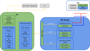
Our new design will include modifying OctoPrint and running our algorithm on a RaspberryPi. Our hardware component will be to construct an RPI shield. However, we will be gathering data from 2 cameras and 2 lasers in order to build a better model of the current print and to provide better cross-checking. Our system will also, over its lifetime, build up a model of the distribution of actual print-errors and inherent errors built into the system (i.e. due to laser and camera calibrations) and assign weights, contributing to the total error that is used to determine whether a particular print is erroneous. Then, the user will be notified and asked if the print should be stopped.

Here’s an updated block diagram:

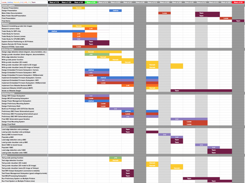
Because of the design change, we also needed to update our Gantt chart:

Joshua’s Status Update for Week of 2/16

What I Did:

Because of our design change late in the week, a lot of the details I did during the week became irrelevant. I was able to implement the optimal camera placement algorithm as mentioned in the previous post, but since we are now using lasers alongside the built-in Ultimaker3 camera, it’s not pertinent anymore. I also began a trade study for an SD card reader that did not lead anywhere because of the design change.

I created a GitHub repo so that code sharing and versioning control could be made easier, but right now it just contains the optimization code.

I made the system block diagram that is seen on our Team Status Update.

I also designed a first-pass power regulation and protection circuit for the RPI Shield (special thanks to 18220, and my eyes for reading the RPI3B+ datasheet and HAT specs). We need protection because new version of the RPI have removed the fuses on the GPIO pins.

Am I Behind?:

I would say that I am behind because the team in general is behind. Because we changed our design late into the Design Phase, we have had to quickly re-refine our requirements, redo our trade studies, and quickly communicate our understand to each other, and I don’t know if we have efficiently done that. However, I believe that once the Design Review is finished, we will be on track to put in our part orders.

Goals for the Upcoming Week:

I get to head up the Design Presentation! Also, I need to order parts required by the RPI Shield. I also need to start laying out the Shield schematic, as well as writing the code that parses the g-code.

Team Status Update for Week of 2/9

We visited TechSpark and talked with Ryan again. He gave us permission to use a Dremel printer for development within TechSpark, but said we would have to use the Ultimaker3 during demo day. He suggested we could create an armature that holds the camera to the calibration screws. He also made note that the Ultimaker3 is a dual extrusion printer, but they only use one extruder; we could put the camera in that second extruder chamber.

We’ve also started to go further into our different trade studies for the different pieces of equipment we will be buying (such as image sensor, camera lens, CPU/MPU/MCU). Also, we refined our testing plan and plan to demo the project. We also narrowed down the actions the user can perform and the types of notifications sent to the user.

Hannah’s Status Update Week 2/9

This week I started to look into all of the different camera systems, and how the different components (image sensor, lens mount, and lens) work together. Based off of some light research, for most error detection systems using some sort of camera, it’s necessary for it to be at least 60 fps. We also care about the power usage and the overall size of whatever chip we get. These requirements were my main focus when looking at different camera/chip systems.

I also began to look up different ways to implement out g-code to 2D image function, and found g-code translator code on GitHub that uses Python to read g-code and produce a 3D graphical representation of the 3D print. I plan to continue looking at this repo more this upcoming week to learn more about what they did, and how they best implemented the different components of the translation.

Hannah’s Status Update Week 2/2

I presented for our Project Proposal, and the feedback we got was extremely helpful. I was proud of myself and my teammates for how we structured the slides and how we answered questions.

Other work that I’ve done this week includes starting the trade studies for different camera modules that we may use in our project. I’m taking a deep look into the physical size of the camera, as well as it’s pixel count & size. There are a lot of camera modules out there that have a bunch of additional features (i.e. shape detection, color blocking, motion detection) that we may want to take advantage of.

Joshua’s Status Update for Week of 2/9

I started the design review slides. In order to determine optimal camera positions, I read Two-Phase Algorithm for Optimal Camera Placement and began implementing its algorithm in Python. There is sort of a steep learning curve, since I haven’t had real experience with optimization techniques. I started off using the cvxpy Python framwork, but got stuck when I realised it could not generate binary integer variables of more than 2 dimensions without clever tricks. I am shifting to using the Python API for IBM’s CPLEX solver (available to me through CMU). By using the process described in the paper and experimenting, we should have a camera arrangement that covers a majority of the print bed. In addition, I started on the block diagram/circuit for the power system and finalized the choice in RF module for the WIFI chip.

The ESP-12F
The ESP-12F contains the ESP8266EX chip, and it can be soldered onto the PCB

Joshua’s Status Update for Week of 2/2

I completed a trade study of various wifi chips. At first I thought we could use the ESP8266EX chip, but after looking further into developing with it, I believe we should move towards using a complete RF module based on the ESP8266EX. I also began a trade study for microprocessors. In addition, I researched and created a list of 24+ types of 3D printing errors, and in preparation for the proposal presentation, narrowed the list down to 4 error classes our device would detect.

Team Status Update for Week of 2/2

After our project proposal, we got a lot of feedback on our project. One thing that we took to heart was that we needed to flesh out our schedule and really narrow down what exactly we need to do, and the steps that we will take to get there. So we completely revamped our Gantt Chart to give ourselves and the instructors a better idea as to what we will be doing each week.

Gantt Chart v2 This week, we focused on doing research for different component trade studies.