Team Status Update for Saturday, Mar. 28

This week largely saw a return to a more normal work schedule, and beginning to act on the updated plan.

Our new timeline to account for the recent changes is shown below:

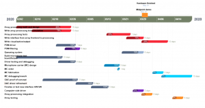
Most components are on track or completed, though there are several components which have fallen slightly behind.  Mainly the computer-side driver to receive and decode data from the FPGA, and the array processing software.  To help get back on track, and since much of the audio calibration/testing has been removed from the scope of the project, Ryan has become more involved with the software/processing side.  John also plans to finish the network driver this weekend.

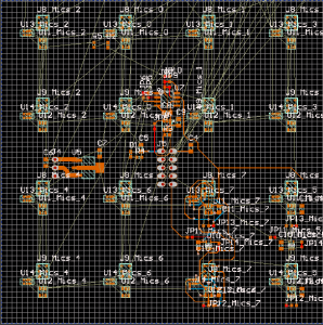
On the hardware side, the architecture of the physical architecture was slightly changed to simplify the design.  Specifically, from having a single carrier board with connectors for each microphone element, to having a small number of boards with many microphones each, that connect directly to the FPGA board using ribbon cables.

Our risk management has largely been reduced the last few weeks, as most of the main risks we foresaw were eliminated over the course of the project so far, or, did not end up being issues.  Our PCB and digikey orders have been fulfilled already, so unless there are problems with shipping, we should have the necessary hardware.  If there are any problems, board design includes several generic alternatives for each critical part, so as long as at least one supplier remains open, we should be able to finish the hardware (see John’s update for more details).  On the software side, risks and mitigations have not changed.

Jonathan’s Status Report for Saturday, Mar. 21

All of the changes to daily life this week didn’t leave much time for work on capstone outside of class, so the additional work completed has been minimal.

Most of what I was able to work on this week was design of the microphone array boards, which was originally scheduled to be finished over the last couple days of Spring Break.

I was able to complete a simple breakout for the microphones, as we’d originally planned to have an array where each element is identical, and on its own small carrier board, with the boards connected to the FPGA with FFC cables.

However, with the changes to the project, I decided this was probably too work intensive to build for a single person to complete, and, difficult to build without the tools we expected to have available.

Instead, the design was changed to a set of 6 boards, each with 16 elements, and a single connector to the FPGA.  This board is still in progress.

This cuts down the total number of components needed significantly, and reduces the number of connectors from about 200 to just six.  The drawback is configurability, if we later find that the 1″x1″ array spacing does not work well, there is not much path to changing it, some workaround would have to be found.  All of the analysis so far has indicated that 1×1 is close to optimal for the frequencies we’ve chosen, but, practical testing will undoubtedly find problems that simulation did not account for.

I have done some analysis of possible workarounds to changing array geometry, mostly pertaining to moving the sub-arrays slightly off-grid relative to each other (so, for example, two array are placed with their nearest elements just 0.5″ apart instead of 1″), which does allow for aliasing and other artifacts to be traded off with directivity, though the tradeoff is often steep in whatever is being traded against (i.e. to gain a little directivity, you have to tolerate significant artifacts, and vis versa).  Hopefully we will not have to do any of this, and all the analysis so far says we won’t, but it is good to know roughly what we’re facing if we do have to.

Photo shows some of the strange artifacts that emerge with unevenly spacing sub-arrays.  The two sources are real sources, so the array is not aliasing, but the sources are no longer round, they are shaped strangely, and, not exactly the same.  The output is still usable, but this illustrates a significant tradeoff of this method of constructing the array.

Team Status Update for Saturday, Mar. 21

This week brought some significant changes to the project, the new scope is summarized in our updated SOW:

Team E0 Statement of Work_3_21_20

Short summary is that the only major changes are to the details of the design, to account for losing access to campus resources, and several tests/characterizations/calibrations of the array will no longer be possible, and will therefore not be performed.

Work will be roughly divided by area, John will construct the physical array, Ryan will write the software to do audio-level processing, and Sarah will write the software to do array-level processing.

With the shutdown of roboclub and most other campus resources, we’ve had to check out most of the tools that we planned to use to construct the project, and set them up an at-home lab.  That along with the mass of changes to all of our daily lives this week has taken up most of our time, so not much more has been completed.

A few things have been done though, some amount of board design for the microphone carriers was done (see John’s update for details), though still in progress, and, the reel of microphones arrived from TDK/InvenSense.

Jonathan’s Status Report for Saturday, Mar. 14

Unsurprisingly there were some significant changes to the progression of the project this week.  Before the switch to online classes was announced, I completed two things for this project, pertaining to the aspect which was slightly behind schedule, the gigabit ethernet.

The Numato PHY was ordered last week, but had not come in by Wednesday, so I decided to freehand solder the ADIN1300 sample that we already had.

The ultimate purpose of this was to debug the RGMII implementation, which should be a lot easier, since we have a full datasheet for the ADIN1300.  To this end, I added a microcontroller to communicate with it over the MDIO interface.

By looking at the errors that came up when attempting to use it, I eventually found that some of the bits were backward (forward for RGMII, but ethernet is lsb first, so the preamble and CRC were backward, though the payload was correct).  Also the CRC computation was slightly off.  Both of these issues were fairly easy to fix, and the end result was that I was able to send UDP packets to my computer.

Applying these changes to the other board (the RV901), got it working as well.  Given the interruption to everything from Corona and that this is working as is, we’ll probably end up using this board for the final device to save time.

The day after I got this working was when all the Corona stuff really started kicking off, so I haven’t gotten much further than this.  I did start on the microphone carrier boards, but the design of that may have to change to deal with suppliers (possibly) not being open.

Jonathan’s Status Update for Saturday, Feb. 29

This week I mainly worked on the design report, and debugging ethernet.

After CDR we had a few comments, one of which was concerning the choice of FPGA.  Based on that, I went through and evaluated whether we should switch up to a newer/larger FPGA.  I did some preliminary checks on the expected size of the final design, as was suggested during CDR.  Since there is very little processing done on the FPGA, it is mostly just used for data acquisition, the required logic took around 30% of the space available, even with an intentionally inefficient PDM filter.

This used some stand-in logic for the microphone acquisition and filtering, but should take similar space to the final filter.

I also worked some with Ryan on the PDM microphones, we were able to get some very basic data off of a microphone (in this case, given an 820Hz sine wave):

One minor change to the plan is that we plan to buy the Numato PHY this coming week, as the GbE development is falling behind.  Other than that, we are still on track.  In the mean time, I will also begin using a simple USB 2.0 interface for the FPGA based on a teensy 4.0, as a stop-gap while working on GbE.

Jonathan’s Status Update for 2/22

This week I mainly worked on getting the gigabit ethernet interface working on a development board, and, put together a board for testing the PDM microphones.

After getting the FPGA toolchain set up last week, I spent most of this week putting together a basic RGMII interface.  A significant amount of the time spent was on the IO.  Since RGMII is a relatively fast DDR interface, in order to meet timing, I had to use ODDR2 blocks for all the pins.  I had never used these before, and had some initial difficulty getting them to work as expected.  Additionally, some of the IO that I was using to verify operation were buffered with 74HC245 bus transceivers, which cannot operate at the 125MHz required for RGMII.  Once I realized that they were to blame for some of the unusual behavior, I removed them from the board and bypassed their footprints with wires.  At this point, the board is able to send a hardcoded UDP packet over the RGMII interface, however, the PHY does not transmit it.  I am not sure whether this is because some additional configuration is required for the PHY, the RGMII is not being generated correctly or something else, and, cannot find a datasheet for the PHY.  I’ve emailed Broadcom, but haven’t received a reply.  Last week I got a sample of a PHY from Analog Devices, which does have a datasheet available online.  If I’m unable to get the broadcom PHY working, I will probably either use the AD PHY, or purchase a breakout board for a different chip (several are available online for ~$40).

I also built a basic breakout board for one of the PDM microphones, and wrote a basic interface using a Teensy 4.0, that sends the raw PDM data over USB.  I did not have time to do any analysis on this data, however.

(close up of the microphone)

(microphone test board.  Dip switches for switching between multiple microphones)

No significant changes to the plan have occurred, and we are still on track.  Our main risk of falling off-track will be that I will have to get at least a basic ethernet interface working, or else pivot to a different interface, within the next week.

This coming week, I plan to mainly work on the ethernet interface.  I’ll be handing off the PDM microphone test board to Ryan and Sarah, going forward, for audio properties and testing data processing.

Jonathan’s Status Update for 2/15

What did you personally accomplish this week on the project? Give files or photos

This week I mainly did simulations of different array geometries, microphone quantities, and spatial distributions.  More of these images are in the team report, but a specific result of note is shown below:

This was a simulation of a single point source set to 4,6,8, and 10 KHz for each set of images, with a 8″x12″ array of 96 microphones.  The upper set of 4 images shows a regular rectangular grid arrangement, and shows clearly visible repeated artifacts (sidelobes) that also appear in a similar grid pattern.   The lower set of images shows microphones randomly distributed in the same space.  In this case, the main lobes are essentially unchanged, but the distinct, repeated artifacts are replaced with a much more macroscopically uniform noise.  The hope was, that removing the periodic spatial component of the array would spread out the sidelobes more evenly throughout the entire image.  Since some areas in the first images have noise floor to spare, it seems that it may be possible to spread the artifacts out into these areas, reducing their peak amplitude at the expense making them larger spatially.  The random distribution did spread out the artifacts almost completely evenly over the entire image, but, did not significantly reduce the peak amplitude, which was the whole point.  We will likely take another look at doing something like this (altering geometry to reduce artifacts) later on in the project, but for now, we plan to move forward with the rectangular array of 96 microphones, as initially planned.

I also set up the xilinx toolchain for a board I already owned, which we plan to use to do some initial proof-of-concept testing for the gigabit ethernet interface.  We expect that to be one of the more significant technical hurdles of the project, and want to get some experience with it before coming up with the final design.  I didn’t have enough time to actually get the ethernet driver working, but, was able to, after some initial difficulties, program the fpga with a basic program.

With our change to primarily pursuing PDM microphones instead of analog microphones, several components of the plan have changed, but, we are still on track under the new plan.

This coming week, I plan to do some basic, proof of concept testing of the GbE interface, to make sure that it will work for our project before we fully commit to that.  I also plan to begin design of the PCB to interface the FPGA board to the microphones, but I do not expect to finish it this week.  If any of the microphones we’ve ordered show up within the week, I plan to begin some experiments and proof-of-concepts with those.