Electrical Developments:
Before getting to the CADDing, I wanted to be sure how we were wiring this all up, and then therefore what wiring space I would need to take into account while making the housings.
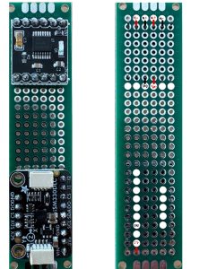
IMU / I2C wirings:

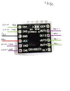
H-Bridge specific Wirings:
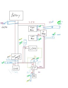
All components wiring diagram updated to included capacitors:
Y-splitting the battery connector out so we can easily distribute to all other parts.
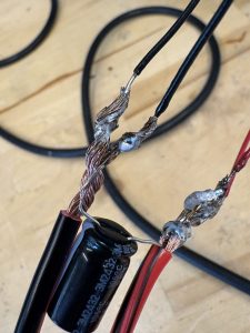
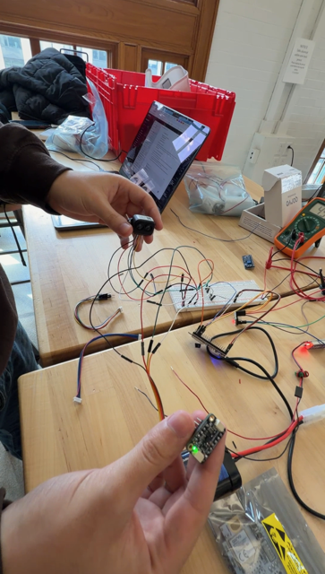
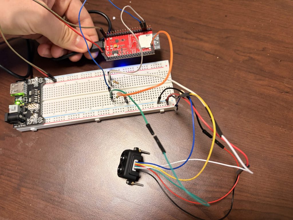
There’s more, and I believe we may have some videos for our team post, but basically I oversaw all the electrical work (so it was a group effort in soldering up all our parts, but I was delegating, as this is the part we’ve ascribed to me having ownership over), and it’s all looking great!! This last complicated one we only did for one battery, as it felt a bit sketchy, but all our motors and sensors have their wires and pins soldered up!
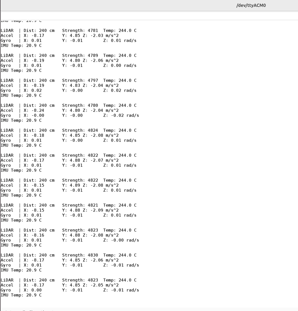
I know we spent a lot of time considering all components, and making sure that it would all work. However, I was pleasantly surprised that when we actually put it all together it just worked. Props to brooks for getting software working near first try!
Housing Developments:
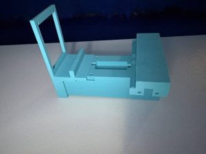
Due to spending more time on the electrical work, the housings are unfortunately not finished yet. It is looking unlikely that a first print will be finished by Monday, but I want to still have a 3D model to show for the presentation (to also talk about improvements/extensions), then a print done Wednesday.
A few new things that also caused reworking:
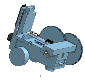
1) our motors are 20 RPM, not 20 RPS. So a gear up is in order. Figured out how to make and port over gears, so now just need to figure out what ratio we actually want/need. (see double_helix gear below, using a plug-in for onshape I found:)

2) we need to order wheels / a ball caster. I thought we could 3D print them, for some reason, but for good grip we really should just order them. I found a good set that should work for all 4 bots, and submitted an order to them. It will take some fenagling to get it on nicely.
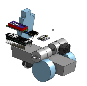
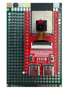
3) our electrical components are rather loose. I was thinking we would make use of the pins as a sort of holder for them, and then use female to female jumper cables, but this takes up a lot of space. Instead, we will be using a series of empty holed PCB boards with mounting holes. This makes it much easier to connect all our components together and hold them in a compact fashion.
current tentative placement of all electrical components (plus wheels) in onshape: