Brooks’s Status Report for 04/25/2026

This week I was the one to give the final presentation for our project. I also worked with my other group mates to finish assembling the final rendition of a catombot once Josh’s final print had finished. Last Sunday, we found that the initial design of the gears required too much torque for the motors to move themselves, but Josh was able to quickly redesign them which ended up being successful. Once we determined that the new gear design was working, I implemented code for tele-operating the motors via commands on a ROS topic. Essentially, the robot subscribes to a velocity ROS topic to which the base station can publish commands that the robot will use to drive the motors. Adrian was able to add functionality to the UI where a user’s arrow key inputs result in the corresponding velocity commands being published to the ROS topic. So, we essentially can now fully tele-operate each catombot.

Our progress is definitely behind at the moment as we approach the deadlines for submitting our final poster and final report, as well as preparing for the demo. We still need to print the housing for another robot as well as solder all the necessary electrical connections so that we can have at least two robots for the demo. Additionally, we still need to get the robot running the autonomous search algorithm, translating search outputs to motor movements, and then test autonomous searching. After this, we also need to refactor some code in the UI and in UWB communication to allow for multiple robots to be used by the system, as our previous work has all been done in order to just get a single robot working.

In the next week, my job will be to fully solder all the electrical connections for a second bot and get UWB locationing and two way ranging working in the context of two robots who are initiators, who will need to both be able to communicate with each anchor as well as the survivor tag. Finally, I will work with the other group members to finalize integration of the system and to finish the poster board, final report, etc.
 

Team Status Report for 04/18/2026

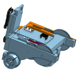
The most significant risk at the moment is that we still do not have a final housing for a robot. As we write this, we have a print in progress for a finalized housing where we’ve worked out all of the remaining issues with the previous rendition which were all related to problems with mounting the breadboard and perf board after having soldered all the necessary connections. The most concerning aspect of this is that we have not been able to test and iterate on any code related to locomotion of the robot.

Since we do not have much time until the final demo, we are attempting to reduce the time we will need to spend working on locomotion by having motor driver code and teleoperation code already written so that we will only have to debug and tune constants once we are able to assemble the housing.

No changes have been made to the block diagram. Regarding schedule changes, the full assembly of the bot has taken longer than previously thought, so all of our testing and final integration will have to take place over this last week.


Brooks’s Status Report for 04/18/2026

This week I finished the plan for all of the point-to-point soldering that needed to be done between the board mounted on the front of the robot and the board mounted on the center of the robot, as well as all of the motor and power connections from the battery. We hadn’t realized how much planning it would to connect the boards in a way that would physically work when everything was actually in the housing, so this task took longer than expected. It took about a day for me to complete all of this soldering, but when it was done I was able to confirm that all of the peripherals were properly connected and working by running our code on the ESP32S3. We still need to repeat the process for an additional bot.

Perf Board Back
Perf Board Front
Board to Board Connections
Solderable Breadboard Bottom

I also worked with Josh to make some modifications to the physical housing that were necessary in order for the boards to sit properly in the housing post-wiring. At this point, the design of the physical housing should be completely done, and we are currently waiting for the print to finish and should have it by tomorrow morning assuming the print goes smoothly. Lastly, I modified the code for streaming camera video from a catombot so that it can now be toggled remotely via a ros topic, which Adrian has integrated into the UI. We can now enable and disable camera streaming to the UI so the operator can see exactly what the robot is seeing.

Overall, the group’s progress as a whole is a bit behind as creating the physical housing has taken much longer than expected. Therefore, I have been trying to work on tasks that don’t require the physical housing to be done, but most of the integration, motor control, and robot control has been blocked by this stage. In order to catch up, Adrian and I will meet tomorrow to pick up the finished housing ASAP to test the software we have been building (autonomous search algorithm, UWB locationing and UI display, etc) as well as completing the motor control. If the autonomous searching is giving us difficulty, then we will instead spend our time implementing direct tele-operations for controlling the robot’s movements for the purpose of the final presentation.

For the final demo, we will need to build and solder another set of components for a second robot , and will need to make sure autonomous searching is functional as well. Since I was the one to plan and solder the last robot, I will be the one to do the second one. So, assembling the second robot will be my first focus, and when done Adrian and I will be working closely together on all of the software to ensure we have a working multirobot system with autonomous searching that displays robot position and sensor data to the user.

Brooks’s Status Report 04/04/2026

This week, I made sure UWB locationing was working correctly and worked on setting up the anchor boards to automatically boot up as anchors. I also finished connecting UWB coordinate calculations to ROS, so now we have a complete range, trilaterate, publish flow that Adrian was able to connect to the UI. Lastly, I moved our project to using PlatformIO with Arduino as the framework. This gives us a number of QOL improvements, e.g. we can now use the rich libraries provided by Arduino and have PlatformIO handle dependencies for us. Unfortunately, there was a lot of work time that ended up getting eaten up resolving some strange UART behavior that was occurring when trying to send and receive CLI messages. This means I was unable to complete the survivor tag locationing.

Since I am now behind on survivor tag locationing, my plan is to spend the rest of tonight and tomorrow writing the pseudocode and initial implementation. I say “initial” implementation because this step, as well as implementing “on-the-fly” anchor calibration somewhat requires that we have a physical bot built. I intend on writing an implementation that essentially has the controller tell the UWB board to attempt ranging with a tag, and then separate those ranging requests and responses from the others with the anchors, however I anticipate needing to modify this code once we can test with a moving bot looking for the tag. Once I finish this, I will see if I can help Josh finish building the first bot and work on implementing Kalman filtering to fuse our IMU and UWB data to improve locationing accuracy. Essentially, I will keep working on survivor tag locationing, kalman filtering, and on the fly anchor calibration next week, but the first and last task won’t be able to be considered “finished” until we are able to verify with a real bot, although I will do as much as possible until then.

Brooks’s Status Report for 03/28/2026

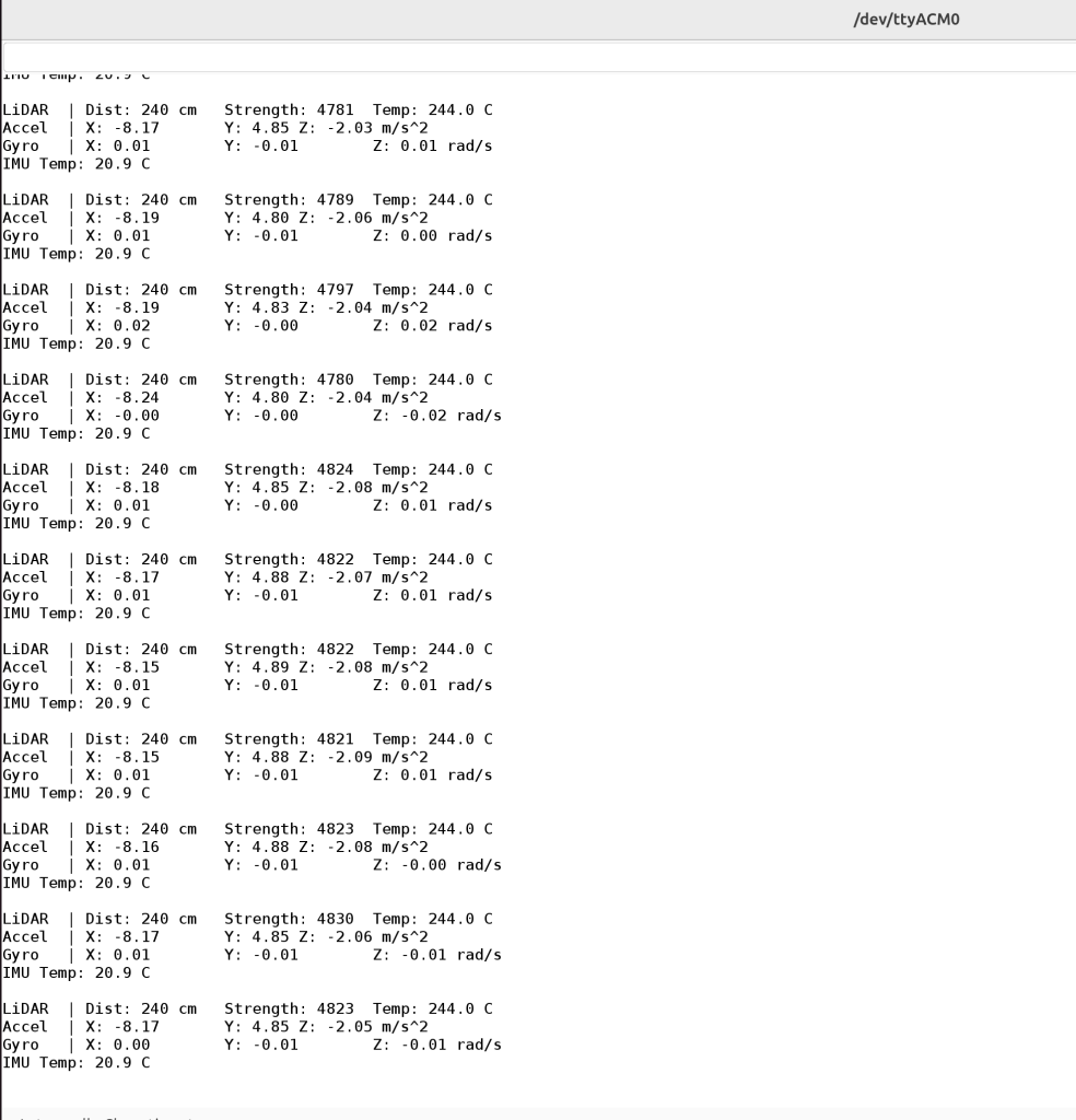
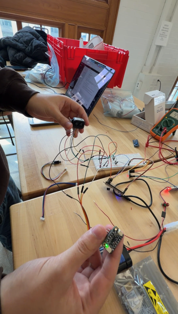
This week I worked on getting UWB trilateration working, and my goal is to have it finished tomorrow. I also helped get the motors / H-Bridge and the IMU working. I also helped with soldering a lot more pin headers to all of our components, so we now have almost all the physical components together, we just need to start soldering to the PCBs and to solder some of the buck converters to the other battery connectors. We also did some basic integration testing where we wired up both the IMU and TFLuna together and ran them both at the same time. Both are connected to the ESP32S3 on the same GPIO pins to communicate over I2C. Lastly, I finally was able to figure out how to get ROS working on my groupmates’ computers so that they can now run the micro-ROS agent on their systems.

LiDAR and IMU Readings
LiDAR and IMU Wired Together

We are on schedule, but tomorrow the group as a whole needs to spend a lot of time together to ensure we are ready for the interim demo and that our systems are in a good spot to show off.

Next week I hope to complete locationing for the survivor tag, which will involve having one non-anchor UWB board being tracked in 2D space, and then having it also range with an AirTag or other UWB board to act as the survivor tag, and then produce the location of the tag by inferring position relative to the non-anchor or tag board.

Team’s Status Report for 03/21/2026

Risks:

There are no new risks at the moment. The biggest risk we anticipate has to do with potential issues coming out once we are able to assemble a bot, e.g. we find out that the voltage regulator is unable to support all the devices, etc.. The main way we are mitigating this is by testing components together when we can, such as testing UWB ranging where at least one UWB board is solely connected to the ESP32S3, which allows us to at least confirm that interconnect between individual modules works. At full bot assembly, this will save a lot of time debugging potential issues since we’ve verified which individual parts should work together.

Design and Schedule Changes:

There have been no changes to our overall design, we are still following the same path as before. Similarly, no changes have been made to the overall schedule. Completion of global frame formation has been pushed to Monday, but the following deliverable of trilateration is on track to be finished at the same time. Therefore, we are still on track for the upcoming interim demo.

Photos:

Initiator board (connected to ESP32S3) returning TWR info
UWB Responder (Connected to computer via USB) Serial Output
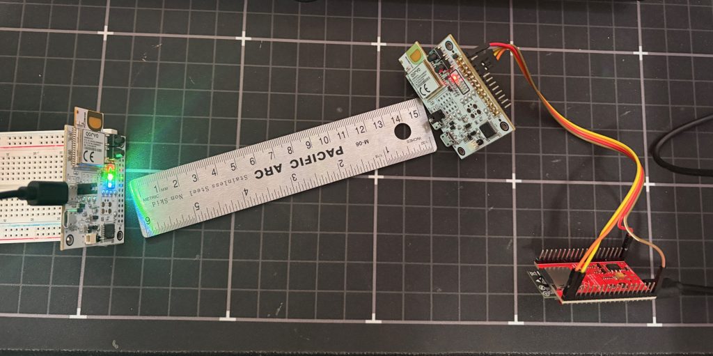
UWB Ranging ~15cm away. Left board is responder (powered by USB), right board is initiator (controlled and powered by ESP32S3)

UI:

LiDAR Working:

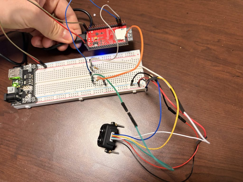
LiDAR wired up to the ESP32S3. Confirmed ESP32S3 was able to read measurements.
Schematic for LiDAR wiring above.

Brooks’s Status Report for 03/21/2026

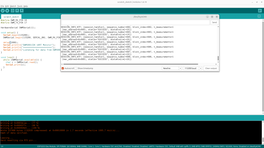
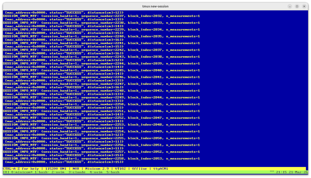
This week I was able to create the ranging UWB ranging pipeline between one of the UWB modules and an ESP32S3. In order to do so, I had to solder some header pins to the DWM3001CDK, and then hooked up the UART pins, 5V, and GND pins to the ESP32S3. The ESP32S3 sends CLI commands and then receives ranging data over UART. After this, I setup one DWM board to be an initiator for TWR while another was setup as a responder. The initiator was connected to and powered solely by the ESP32S3, while the responder was connected to my computer over USB. With this setup, I confirmed from the ESP32S3’s serial monitor that the ranging data was successfully being picked up. Lastly, I also set the UWB modules to be roughly 15cm away from each other and confirmed that the measurements were, on average, accurate.

TWR Ranging Setup. Left board is responder, right board is initiator
Initiator board (connected to ESP32S3) returning TWR info
UWB Responder (Connected to computer via USB) Serial Output

Regarding scheduling, I am behind on implementing formation of the global frame as this was supposed to be completed by today, however to compensate I plan on spending additional slack time tomorrow working on this. The primary concern in falling behind on this task is that the trilateration implementation requires the anchor boards to have coordinates assigned to them, and so a coordinate system is needed. However, this can technically be solved temporarily for trilateration testing purposes by assigning an arbitrary origin and axes. Therefore, my plan is to allow myself until Monday night to complete global frame formation. If I’m unable to completely finish it by this point, then I will move onto implementing the trilateration algorithm and plan to test by assigning a corner of the Hamerschlag room that our group works in, and define the axes myself. I gave myself longer than what should be necessary to implement trilateration (the algorithm is pretty straightforward), so I hope to finish that part early, giving me time to return to global frame formation if need be.

As mentioned above, the deliverables I hope to complete next week are global frame formation and trilateration, but I will prioritize trilateration if global frame formation takes me longer than Monday to complete.

Brooks’s Status Report for 03/14/2026

The main work I did this week was completing the task of getting microROS and ROS2 completely setup as well as reading a lot of documentation for the Qorvo DWM3001CDK module. Regarding the ROS setup, I was able to successfully publish an increasing integer over WiFi from the ESP32S3 DevKit and then have a ROS agent on my computer receive it. This means we now know we can successfully publish UWB ranging information once we are able to connect the ESP32S3 to the DWM3001CDK.

Running microROS Agent
Serial Output of ESP32S3
ROS2 Topic: int32_publisher Talker
ROS2 Topic: int32_publisher Listener

As for the documentation for the Qorvo DWM3001CDK, I had previously had problems finding the documentation needed to begin programming on the board as the website only provides a simple product brief. However, after we received our boards this week, I requested the SDK from Qorvo which, after unzipping, I found contained all of the documentation we would need to work with the product. The SDK includes a firmware version they call the “UCI” version which has an API for sending commands for initiating TWR sessions. Given that we don’t want to have to write custom firmware for the UWB modules, this firmware version seems to fit our needs the best and will be the firmware I plan on using for implementing the pipeline between each ESP32S3 and DWM3001CDK. I was able to successfully start the board on this firmware and have it search for other UWB modules, but I did not run another module at the same time because, at that stage, I just wanted to see that I could get one working.

DWM3001CDK Initiation running the UCI Firmware
Example Ranging Output from the DWM3001CDK

I am not yet behind on schedule, however I now only have three days to complete the pipeline between the UWB modules and the ESP32S3’s. Now that I know what I have read the necessary documentation for interacting with the DWM3001CDK, I know that I have to write a library for serializing command messages from the ESP32, deserializing the responses from the DWM3001CD, and then packing that into a format to be published as a ROS topic that will be consumed by the UI Adrian is implementing. I plan to spend most of tomorrow working strictly on getting this up and running so that Adrian is no longer blocked by this task.

In the next week, I hope to complete the basic implementation of the ranging pipeline so that I can work with Adrian to begin connecting real ranging measurements to the UI. Additionally, I will begin working on the locationing / global frame formation using the completed ranging pipeline.

Brooks’s Status Report for 03/07/2026

This last week I continued working on getting microROS and ROS2 working on my machine and on the ESP32. Since ROS2 is not well supported on platforms other than Ubuntu, I had to spend a while getting my dual-boot setup to work but I finally got it all set up. After I had my Linux environment setup, I spent some more time researching the setup for microROS on an ESP32 and found that I had to install the older v5.2.6 version of the ESP-IDF. Then, I found out that the ESP-IDF VS-Code extension is bugged on the snap version for VS-Code (the one you install from the Ubuntu app store) so I had to get the .deb package from the VS-Code website and install it using apt. That finally got everything to work on the ESP-IDF side. Then, I was able to install and use the Jazzy-Jalisco version of ROS2 for Ubuntu and was successfully able to create a ROS publisher and subscriber with the subscriber reporting back all the published information. So, in a nutshell, I got the entire development environment back up in Linux and was able to get ROS to work just on my laptop.

Progress is on schedule, I said that I would have been able to figure out how to have a microROS client running on the ESP32-S3 by the end of tomorrow, which works perfectly as that should all be straightforward after doing all the required setup this last week.

For next week, I will hopefully be able to implement the two-way ranging pipeline between an ESP32 and a Qorvo DWM3001CDK. I say hopefully as this will depend on whether or parts do in fact arrive next week with ample time to finish this step. We ordered the DWM3001CDK kits from Digikey last week so they should arrive in time for me to complete this deliverable. Until the parts arrive, my plan is to help my teammates with their deliverables as needed and try to find more documentation for the DWM3001CDK. In particular, I did not see a software/programming guide for the board on the website so I’d like to find documentation for how one interacts with the board. If I still have extra time, then I’d like to start writing the C code for performing trilateration as this can definitely be done without having the components yet.

Part B: Please write a paragraph or two describing how the product solution you are designing will meet a specified need with consideration of cultural factors. Cultural factors are encompass the set of beliefs, moral values, traditions, language, and laws (or rules of behavior) held in common by a nation, a community, or other defined group of people.

Our project is a small multi-robot system designed to assist with urban search and rescue operations by quickly exploring collapsed or hazardous environments where sending human responders would be dangerous or slow. While the system’s design first and foremost addresses the need for faster and safer disaster response, cultural factors can influence how our project should be designed and deployed. Disaster response can involve coordination between different agencies, communities, and sometimes international teams, each with their own norms, communication practices, and operational rules, i.e. cultures. Our design prioritizes simple operation and clear reporting of information via a simple UI so that responders from different backgrounds can easily integrate the system into their efforts. By keeping the system accessible and easy to operate, the design can help ensure the technology can be used effectively while respecting the expectations and procedures of the communities it would serve. If time permits, our design could further address cultural factors and differences by providing different language options for the UI

Team Status Report for 2/21/2026

Risks:

Right now, our biggest risk is whether our power distribution plan actually works the way we expect. If it turns out our current approach isn’t sufficient, we’d need to revise the design and order new components, which could slow down full prototype integration. That said, this isn’t immediately blocking us. Most subsystems (UWB comms, microcontroller setup, UI work, etc.) can still be developed over USB power. Power becomes critical once we start integrating locomotion and running the full search stack, so we have some buffer before it affects system-level progress.

Design and Schedule Changes ?

No changes were made to the system design this week. All major revisions to our use case and corresponding design updates were completed last week, so we’re continuing forward with that finalized architecture.

Since there were no new design changes, our schedule remains the same heading into this week.

On the implementation side, we made solid progress. We got the ESP32-S3 devkit fully up and running in the ESP-IDF VSCode environment with clean build/flash/monitor workflows.  Also, we figured out how to debug directly on the board using GDB, which will help a lot once we start diving into programming our robots. On the hardware side, we secured access to 2S LiPo batteries and selected voltage regulators for distributing power to different subsystems.