
This week I completed assembly and initial testing of the 555 timer interrupter circuit with audio modulation capability. I soldered all components including the duty cycle potentiometer, timing capacitors, and the 3.5mm audio jack with DC blocking capacitor. During unit testing with the oscilloscope at TechSpark and the 220 lab, we discovered the interrupter frequency range stays on target in the expected 20kHz+ range, however the duty cycle is running too high with the minimum duty cycle at 40%. This needs to be corrected for proper audio modulation. Next week I’ll debug the interrupter circuit to adjust the duty cycle range down to the designed specifications, then work with the team to complete full system integration testing.
Team Status Report for 03/21/2026
This week the whole team performed unit testing on the circuit componentry. There was an issue in the interrupter circuit which has been identified as improper resistor values. A new interrupter circuit is currently being built to fix this issue, as duty cycles were far too high originally. This will result in a minor design change regarding the resistances used in the interrupter circuit, however those values have not been chosen yet. When they are, a post with an updated design report will be made to reflect those changes.
Once a new interrupter module has been built and passes unit testing for frequency and duty cycle range, the components will be assembled for integration based testing. We as a team plan to perform a large majority of the integration testing in one long period, which will serve as an apt stress test of our design as well.
As of current our biggest risk is integration. The time taken to perform these tests is non-negligible. While we do fear this may eat into our time to design our housing, we believe that we can power through. We still plan to have an at least basic functioning model by the interim demo date. An updated schedule will be included in the updated design report when that has been made.
Caleb’s Status Report for 03/21/2026
This week the whole team met and performed unit testing on the individual components of the broad circuit. We came across issues with the circuit that are currently being worked on and have halted further progress towards integration. One other issue identified was heat management, as such all ICs now have heatsinks, and a fan will be implemented in the final housing.
Circuit debugging is expected to be finished Monday so that unit testing may be finalized. Once that is done I plan to assemble the components together on Tuesday so that on Wednesday we can perform broad system testing and tuning, which has unfortunately been pushed back.
Jack’s Status Report for 3/21/2026
This week all three of us met up at TechSpark as well as the 220 lab for unit testing. We used devices such as the multimeter, oscilloscope, as well as wave generator to test both the primary and secondary coil and the designed circuit that we’ve soldered onto the board. We did witness errors, which was within our expectation for initial part testing. These errors will be describe in detail in the team weekly report. Next week we are aiming to debug what we’ve built, and once that is done, we are going to assemble the parts together and shoot for final overall testing.
Jayson’s Status Report for 3/14/2026
This week I finished assembling and testing the 555 timer interrupter circuit with audio modulation. The circuit functions properly when tested standalone – duty cycle modulates from 35Hz to 35kHz and the 3.5mm audio jack accepts input signals correctly. However, I’m encountering integration issues when combining it with the oscillator and gate driver circuits, likely due to grounding or timing problems. Next week I’ll systematically debug these interfaces with the oscilloscope and coordinate with Caleb on proper grounding between circuit boards.
Team Status Report for 03/14/2026
This week we managed to complete all of our assembly tasks. While an issue with a soldering iron kept us from getting back on schedule perfectly, we established our schedule with enough time in each task to allow for some play. Next week will be some broad scale testing completion.
Our greatest threat to completion is integration error currently. With coil winding out of the way now, we plan to run unit tests on individual circuit components to ensure that each is outputting properly before we combine each into one single assembly.
No changes have been made to the design or schedule, but you can find a picture of the completed componentry here in this post.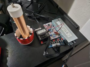
Jack’s Status Report for 3/14/2026
I helped build the circuit. My primary work was wrapping the coils for the Tesla coil alongside Caleb, where I was the wrapper for the primary coil and the person keeping track of the number of turns on the secondary coil (456 turns). I’m a bit behind schedule as we haven’t started testing. I will start testing this upcoming week.
Caleb’s Status Report for 03/14/2026
This week I completely assembled and soldered all of the circuitry components. This took longer than expected because of a defective soldering iron, but I did still manage to get it done. While yes I am behind schedule, my schedule is written with enough time throughout each section to allow some room for error. I hope next week to finish thermal testing.
Team Status Report for 03/07/2026
Throughout the last two weeks, all parts were delivered, though many of the circuit components have not yet been received. While this does place us slightly behind schedule, we intentionally spaced our schedules in such a way to allow for some timing errors to happen, and believe that it should not create much affect. Coil assembly is underway, and is expected to be completed alongside circuit assembly when we meet on Monday 03/09/2026. Then the rest of the week can be dedicated to testing.
The current greatest threat to success that has been identified is proper winding of the secondary coil. The wire is thin, and many windings must be made tightly, however this is being done by hand, so some error is expected. This issue has already been accounted for though; we gave the Schmitt Trigger Oscillator such a large tuning range to account for resonant frequency misalignment between the coils, which we expected to be exacerbated by manual assembly.
One minor change has been made to the design, which is the inclusion of hot glue and electrical tape to hold the coil windings in place. Again, following from manual construction, it is very difficult to keep the windings in place without some form of adhesive.
Though we are slightly behind schedule, this was somewhat expected, and as such, no changes have been made to the schedule.
We were also asked to describe the product again in multiple ways, and these descriptions can be found below. Description A was written by Jayson, Description B was written by Jack, and Description C was written by Caleb.
A) The Musi-Coil system was designed to address a need that exists beyond the academic setting, which is making high-voltage electrical phenomena accessible, safe, and engaging to general audiences. Traditionally, Tesla Coils have been large and dangerous, only operable by specialists with significant training and access to industrial facilities. This design deliberately deviates by using a safe 48V supply, and much smaller coils, which will produce arcs that are visually striking but don’t carry large enough amounts of power to significantly harm someone. This makes it suitable for usage anywhere, be that schools, public maker spaces, or at home, not just in industrial labs.
The audio modulation capability further broadens the Musi-Coil’s global appeal by transforming a purely technical demonstration into an artistic medium. The ability to play recognizable music through plasma attracts significantly more attention, and makes it more engaging to a broader crowd, not just those who already understand the underlying electromagnetic principles. This allows the Musi-Coil to serve as a device for boosting overall STEM engagement worldwide, serving to increase STEM engagement which is extremely low in many areas globally. By using readily available, off the shelf components, the design is reproducible by hobbyists but also affordable, which reduces the barrier to providing more interesting and exciting ways to get people to engage with physics and electrical engineering.
B) Though the Musi-Coil isn’t explicitly suited for this purpose due to its compact size, it serves as a prototype for more culturally impactful implementations, such as in entertainment installations like night clubs or live music venues. Night club culture often emphasizes immersive audio-visual experiences where lighting, music, and visual effects work together to enhance the atmosphere of the performance. Because the product generates visible plasma arcs in response to music, it could be scaled up and integrated into stage or club environments as a unique visual implement. With an installation this large, the arcs would modulate with the music, creating synchronized electrical discharges that visually represent the sound being played. This aligns well with nightclub culture where audiences value novel and dramatic visual effects.
However, cultural expectations surrounding safety and accessibility would still need to be considered. Music venues are typically densely populated spaces with large audiences, so any scaled version would require appropriate shielding and arc-control mechanisms to ensure safe operation, especially for those with devices such as pacemakers. The current design already prioritizes controlled arc length and stable operation, though using methods which may not translate as well to larger installations. Regardless, by considering both entertainment and safety norms, the Musi-Coil could serve not only as an educational demonstration but also as a culturally relevant visual performance device.
C) The Musi-Coil has only one major implication on the environment, power consumption. As is well known thanks to decades of research on global warming, higher power consumption items produce a higher need for power production, which in most areas is not done using clean energy. While the Musi-Coil is not nearly large enough to create a noticeable spike in strain on the grid or increase in power consumption needs, it is considered good practice environmentally for all people to consume less power personally. As such, the Musi-Coil meets this good practice through a very efficient design.
In designing this high voltage product, a major concern was power efficiency. Since we intended for this to serve primarily a demonstrative purpose, we needed the Musi-Coil to be usable in any commonplace setting, and operate properly when plugged into a wall. This meant power consumption needed to be kept low enough as to not trigger a standard breaker, which trips at 1600W. What also influenced our power consumption decisions was user safety, as even though our product produces high voltage, if it did so with too much power, it would be inherently more dangerous and less controllable. As such, current peak power consumption estimates are only at around 350W, which is equivalent to the charger for a typical high end gaming laptop. Thus we believe that even though the Musi-Coil is not designed to serve some environmental purpose, it is designed to be environmentally friendly.
Jayson’s Status for Report 3/7/2026
This week I received the secondary coil components and began assembly, the topload has been installed, and all that is left to do is coil wrapping, but working with PVC pipe, I have come to realize that the wire doesn’t stay in place well and some adhesive may need to be used. Though I am slightly behind schedule, I believe this will be done by monday so that I can hopefully perform interference testing next week.