Caleb’s Status Report for 04/25/2026

This week I performed the final topload testing. We purchased three more sizes of topload to use, finding that the 1.5 inch diameter sphere was optimal. This was still not enough inherently however, but was the closest we came. What finally ended up producing successful results was adding a small spike to the top of the coil. Then I performed some basic testing.

I think we have finally made it up to schedule. Theres only really one thing remaining to do which I will be doing throughout the next week. This is an improvement to the cooling system, more specifically cooling the MOSFET in order to permit higher duty cycles or frequency without overheating.

Caleb’s Status Report for 04/18/2026

Over the last two weeks an enormous amount of progress has been made. First, after having successfully solved the dead gate driver issues, we then had a MOSFET die. The cause was identified as V_GS going out of range. This was resolved through a two-part solution. First, the output line of the gate driver was given two clamp diodes, one to VDD and one from GND. This effectively limited the output voltage of the gate driver from -0.3 – 12.3V, well within the MOSFET’s operating range. Second, the MOSFET source is connected to the ground terminal of the 48V power supply, which was not directly tied to the control circuit grounds. This was initially viewed as a non-issue, however, when resolving this problem, I realized it was possible that source was not at 0V relative to the ground of the gate driver. In testing it was found that, while there was no DC offset between the two grounds, ringing was causing voltage transients up to 20Vpp to appear on the MOSFET source. This was quickly resolved by tying the grounds of the two power supplies, forcing a unified reference voltage. This week in specific, I also managed to finish 3d printing, and nearly finish assembling the product enclosure. There are also some things to mention regarding the coils, though that is better saved for the team’s report.
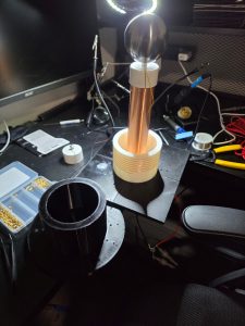
We have been behind schedule for weeks. And technically, here at the end of official work time, we still are by about a week. What remains is final integration and assembly. However, we do not intend to stop just because the final presentation is this coming week. As such, tomorrow, we will be doing final integration items, in hopes to include a success result in our presentation, and certainly our final demos.

By the end of this coming week we will have it fully assembled, and hopefully we will successfully have achieved our MVP.

Caleb’s Status Report for 04/04/2026

I’ve spent much of this week attempting to debug the gate driver circuit, and unit testing the others. The audio modulation input is confirmed to work. The coil circuit is also confirmed to work and does switch at an appropriate rate. The current issue is the gate driver. At this point I am undeniably behind schedule. Next week I plan to have the gate driver fully debugged and perform full integration of the circuit, this way we can focus our efforts in the last couple weeks on final integration tests and housing assembly.

Calebs Post for 3/28/2026

This week I performed a large amount of testing as well as fixed the interrupted circuit. Aside from a chip that blew, the gate driver circuit works perfectly (and will not blow a chip anymore). Also I discovered an issue with the primary coil, who’s inductance is much higher than intended.

This coming week I the primary coil issue will be resolved and I will be conducting integration tests. I believe we are pretty much back on schedule, minus the integration not being completed yet.

Caleb’s Status Report for 03/21/2026

This week the whole team met and performed unit testing on the individual components of the broad circuit. We came across issues with the circuit that are currently being worked on and have halted further progress towards integration. One other issue identified was heat management, as such all ICs now have heatsinks, and a fan will be implemented in the final housing.

Circuit debugging is expected to be finished Monday so that unit testing may be finalized. Once that is done I plan to assemble the components together on Tuesday so that on Wednesday we can perform broad system testing and tuning, which has unfortunately been pushed back.

Caleb’s Status Report for 03/14/2026

This week I completely assembled and soldered all of the circuitry components. This took longer than expected because of a defective soldering iron, but I did still manage to get it done. While yes I am behind schedule, my schedule is written with enough time throughout each section to allow some room for error. I hope next week to finish thermal testing.

Caleb’s Status Report for 03/07/2026

Spring break was this week, as such, this report will encompass the week of 02/22/2026 as well. Components for both the primary and secondary coils have been received, as have the power components and some of the circuitry components. Though the rest of the circuitry components have been delivered, nobody was available to receive them. As such, the circuitry has not begun assembly yet unfortunately. This means I am personally behind schedule. I am not overly worried about this, however. Judging by the size of the circuitry and how it will be assembled, I estimate that I can complete it on Monday 03/09/2026, and that will leave time for thermal testing, which I hope to have completed by 03/14/2026.

Caleb’s Status Report for 2/14/2026

This week I finished up the trigger circuitry. I am of the belief given the research and calculations which I have done that this will provide the appropriate output necessary to drive the MOSFET gate in such a way that class E operation of a solid state tesla coil will be properly achieved. I also had a bit of extra time this week so I began working with the coil. Using a program called JAVATC I have come up with what I believe will be reasonable and functional dimensions and build specifications for both the primary and secondary coils.

Caleb’s Status Report for 2/7/2026

I have worked out what I expect will be a functional output circuit that takes the signal from the interrupter and provides it to the primary. The trigger has been fully designed, and an IC has been selected for the MOSFET Driver, however some quantitative values of circuit elements such as resistances and capacitances have yet to be calculated for.  Appear to be on schedule.