Justin Bell Status Report 4/25/2026

This week I switched the Nav2 local controller from Regulated Pure Pursuit (RPP) to the Dynamic Window Approach (DWB) controller. RPP had been working but showed consistent issues near the goal, the robot would oscillate and fail to converge when it got close, partly because RPP computes a single curvature command along the path and doesn’t sample the velocity space dynamically. DWB samples a set of trajectory candidates at each control cycle, scoring them against a set of critics (path alignment, goal heading, obstacle clearance, etc.), which gives it more flexibility for stopping cleanly and recovering from heading errors.

The SparkFun OTOS node publishes in inches internally and converts to meters with the * 0.0254 factor on both linear.x and linear.y. The main tuning work this week was on the linear and angular scalar calibration exposed by the OTOS firmware.

To tune these, I drove the robot a known distance (measured by tape) and compared against the OTOS-reported displacement, then adjusted the scalar proportionally. Same process for angular: rotate a full 360 degrees and check that the heading returns to within a degree or two of zero. These scalars live in the otos_odom_node.py startup block just after calibrateImu().

Justin Bell Status Report 4/18/2026

This week I spent a good amount of time working on the odometry sensor. It was reading about 90 degrees off from where it should have been, which was causing some issues with how the robot understood its own orientation. I went through the recalibration process to get it lined up correctly so that the heading data coming from the sensor actually matched the real world. Once that was sorted out, I also worked on calibrating the motors. The drive behavior was not quite where it needed to be, so I made some adjustments to get the left and right motors responding more consistently and accurately to velocity commands.

On top of that, I made some changes to the local costmap configuration. Specifically, I increased the inflation radius so that obstacles get bigger bubbles around them during path planning. This should help the robot keep a safer distance from walls and objects instead of trying to squeeze through tight gaps. I also took some time this week to test out the pan tilt system, running it through its range of motion and making sure it was tracking and responding properly. Overall it was a productive week focused on tightening up a lot of the core subsystems on the robot.

A lot of what I have been learning this semester has come from a mix of self teaching and prior experience. For the SLAM side of things, I learned how to use Google Cartographer by watching videos and reading articles online, working through tutorials and documentation to understand how it processes lidar data and builds occupancy grid maps. It took some time to get comfortable with how all the parameters and configuration files work together, but the online resources were really helpful in getting me up to speed. On the FPGA side, a lot of that knowledge came from a previous internship where I got hands on experience working with FPGA development tools and hardware design workflows. That background has been really valuable for this project, especially when it comes to working with the Kria board and understanding how to integrate hardware accelerated components into the overall system.

Justin Bell Status Report 4/4/2026

The pan-tilt camera is operational and reacts to RPLiDAR detections within 0.3 meters. Upon detection, the camera orients toward the detected angle to determine whether the object is a person. The detection pipeline also evaluates bounding box aspect ratio to classify posture — a ratio greater than 1.0 (wider than tall) flags the person as laying down. This result is broadcast as part of the alarm system. Both pan_tilt.py and the laser TF broadcaster are running on the robot.

Autonomous navigation is partially successful. The Nav2 motor bridge translates cmd_vel Twist messages into left/right wheel commands via differential drive kinematics, driving the VNH5019 motor controllers through lgpio on gpiochip4. Direction is handled by INA/INB pins and speed by PWM duty cycle, with a 0.5-second watchdog that cuts motor output if cmd_vel stops publishing. After adjusting Nav2 parameters to reduce reliance on odometry, the robot has shown improved course-keeping under the new configuration.

Video

Verification:

I performed verification tests for Computer vision, mapping, and basic navigation. Computer vision testing involved taking multiple people, water bottles and backpacks in front of the camera and seeing what the model determined they were. For people, it also was tested on it’s ability to recognize if they were fallen or not. The model worked properly and reliably outside of the case of Paul laying down in a red Oberlin hoodie, where he was occasionally identified as a couch. When a fallen person was identified, I made sure that the audio played properly. We also plan on implementing running detection, and then testing it, which has not been done yet. Similar to the fallen person testing, we simply need to verify that it can detect a person moving rapidly. Mapping testing involved running the robot through an area to be mapped and observing the resulting hard/soft obstacles and comparing them to the actual room layout. This was done in HH 1307 and just outside of it. We found that the higher the concentration of glass and small objects like chair legs, the worse the mapping performed. This was also where we found that ~0.15m/s would lead to the least blurry maps. Basic navigation testing involved taking a point on the map and directing the vehicle to move to it, which was successfull outside of 1307. However, this testing will be expanded by using different locations with less glass and a lower density of small objects. After we perform more mapping and navigation testing and can improve them, we are essentially done and have completed our design and use case requirements.

I also performed lidar testing with sean and Paul. We first moved multiple objects and ourselves around the stationary vehicle, where we found that it could recognize the changes in position, though there was a slight delay. However, when moving, especially in areas with glass, the quality of the distance map decreased, likley due to that delay. If Lidar does not work, then we cannot localize, so it is required for navigation and mapping to ever work.


Justin Bell Status Report 2/28/2026

Progress Report

The Kria KR260 was pose detection was made and tested .The detection pipeline was extended to include bounding box aspect ratio analysis for laying down detection, with a refined heuristic combining bbox size, position in frame, and aspect ratio to filter out false positives from partial body detections. On the Pi side, a ROS 2 detection bridge node receives these detections and triggers an espeak voice alarm over a Bluetooth JBL Go 4 speaker when a person is detected on the ground, with a cooldown to prevent alarm spamming.

Motor control was brought online using the Pololu VNH5019 dual motor driver, interfaced directly to the Raspberry Pi 5 GPIO with 8 control pins per the standard INA/INB/PWM/EN configuration. The motor power and logic grounds were verified to be correctly referenced through the shared internal ground plane on the driver board. Nav2 was integrated with the motor control stack, enabling the robot to receive and execute navigation goals. Google Cartographer SLAM was also brought up and is partially functional.

The RPLiDAR serial timeout issue was resolved by replacing the hardware with a new unit, after which the LiDAR, Google Cartographer SLAM, Nav2, and motor control all came together into a functioning navigation stack. The robot is now capable of building a map in real time while navigating autonomously with motor control through the VNH5019 driver. Currently active work is focused on integrating the pan-tilt camera mechanism to enable the robot to track detected persons as it navigates, with the PAA5160E1 optical odometry sensor already running and feeding into Cartographer for improved localization accuracy.

Justin Bell Status Report 3/21/2026

This week I made significant progress on my capstone project across several fronts.

On the perception side, I developed pan-tilt camera code that reacts to LiDAR detentions within 0.3 meters, orienting the camera toward nearby objects to determine whether they are people. I also set up a GitHub repository for the project to keep everything backed up and version-controlled.

On the navigation and hardware side, I continued testing Nav2 and ran additional experiments to evaluate its behavior in real-world conditions. I also swapped out the previous motors for VNH motor drivers and began testing the robot with them for the first time, verifying that the new hardware performs as expected.

3/14/2026 Justin Status Report

This week the main focus on the robot side was getting the full Nav2-to-motor-control pipeline working on the Elegoo Smart Car V4. The Arduino UNO was reflashed with a custom serial listener that parses L<int>,R<int> commands over USB, replacing the stock Elegoo Bluetooth firmware. The V4-specific TB6612FNG motor driver pin mappings (PWMA=5, PWMB=6, AIN=7, BIN=8, STBY=3) were confirmed and wired up. A Python ROS2 bridge node on the Pi 5 subscribes to Nav2’s /cmd_vel topic, computes differential drive kinematics, and sends the resulting left/right motor values over serial to the Arduino. Debugging covered serial port conflicts between the RPLiDAR (/dev/ttyUSB0) and Arduino (/dev/ttyUSB1), fixing the DTR reset delay caused by the UNO bootloader hanging for about 2 seconds on serial connect, setting up a static IP on the Pi via netplan for reliable SSH, and manually testing motor response with ros2 topic pub. The full Nav2 stack is now confirmed running with Cartographer, RPLiDAR, velocity smoother, controller server, and the OTOS odometry node all active.

On the Kria KR260 FPGA side, the YOLOX-Nano post-processing and NMS pipeline was worked through in detail for the HLS implementation. The post-processing stage decodes raw DPU outputs into pixel-space bounding boxes by applying grid offsets and stride scaling, then computes detection confidence as sigmoid(objectness) multiplied by softmax(class logits). The NMS stage runs class-agnostic greedy non-maximum suppression with an IoU threshold of 0.45, using fixed-point arithmetic for hardware efficiency. An HLS C++ testbench was written with 8 test vectors covering edge cases like empty predictions, threshold saturation, injected person detections, multiple classes, and different image dimensions, with tolerances set at 2 pixels for bounding boxes and 0.05 for scores to account for fixed-point quantization error. The detection output pipeline was also switched from serial to TCP over WiFi, with the Kria sending JSON-formatted person detections to a listener node on the Pi that publishes them to the ROS2 person_detections topic.

Justin Bell Status Report 3/7/2026

This week I worked on getting the full autonomous navigation stack running on the robot. Most of the time was spent debugging the ROS2 TF tree on the Pi 5 — Cartographer needs a specific chain of coordinate transforms (map -> odom -> base_link -> laser_frame) and getting all of those publishing correctly without conflicts took a while. The main issues were the robot_state_publisher broadcasting stale timestamps for the laser frame, and Cartographer conflicting with the OTOS odometry node when the wrong frame was set as the published frame.

Once the TF tree was stable I integrated the SparkFun OTOS optical flow sensor as the odometry source for Cartographer. Got it publishing over I2C, converting units correctly, and matching the QoS settings Cartographer expects. Did some test mapping sessions and got a clean room map — sensor height matters a lot, table height produced much better maps than floor level because the LiDAR could see clean wall-to-wall without furniture legs getting in the way.

After mapping I set up the full Nav2 navigation stack. Decided to use Cartographer in localization mode instead of AMCL since the Pi 5 has enough CPU headroom and it gives better accuracy. Wrote all the config and launch files for that.

Also wrote the motor controller node for the VNH5019 drivers using hardware PWM at 20kHz so the motors don’t whine, and the full human protocol system,  a detection bridge node that reads JSON from the Kria over USB serial, a protocol manager that implements all five behavioral responses (normal, people nearby, fallen person, running person, crowd), and a speed limiter that sits between Nav2 and the motors to enforce speed limits per protocol. LED and buzzer control through GPIO is in there too.

Still need to physically mount the sensors on the chassis, wire up the motor drivers, and do a full end-to-end test with everything running together.

Justin Bell Status Report 2/21/26

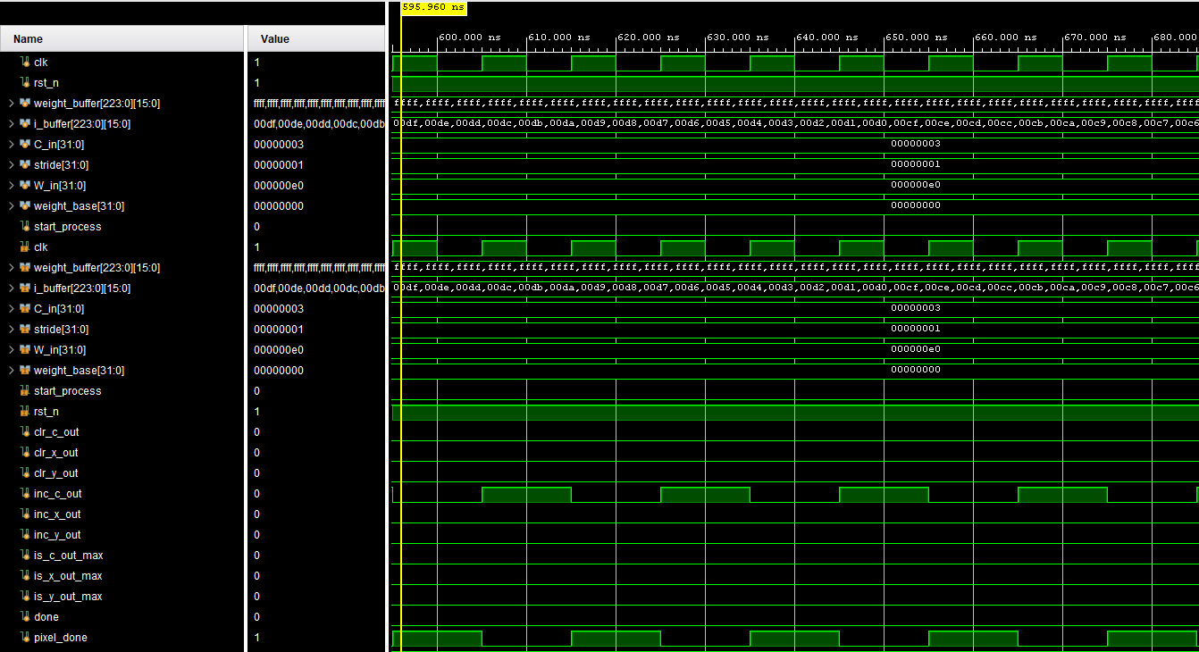
This week was pretty much all about getting the convolution unit to actually do what it is supposed to do. A big chunk of the time went into debugging the hardware itself, making sure the FSM handles chunk-based MAC accumulation correctly, the pipeline latency between when the last MAC fires and when pixel_done asserts is actually valid, and that the buffer addressing is not silently truncating and causing aliasing issues. The whole chunked approach where you tile across K x K x C_in inputs spread across 64 MACs per cycle is solid in theory but has a lot of edge cases to shake out especially around accumulator clear timing and handoffs between output pixels.

On the software side you put together a numpy golden reference script that runs both 3×3 and 1×1 INT8 convolutions from scratch and dumps hex outputs you can feed directly into your testbench. The idea is to have a clean bit-accurate ground truth to compare against hardware readback so you can actually say these match instead of just eyeballing things. The plan is to eventually extend that into a full pytorch-backed reference flow where you can pull the actual YOLOv3-Tiny weight tensors and run them through the same pipeline so verification stays meaningful as the design matures.

The bigger picture goal tying all this together is getting every piece of the CONV2D pipeline working as a unit, not just the MAC array in isolation but the whole chain with bias add, requantization, leaky ReLU, and eventually maxpool feeding into the next layer.

Justin Bell Status Report for 2/14/26

This week I revisited the convolutional layer in my YOLOv3-tiny hardware implementation and realized that the original conv_2d module was not properly parametrizable for the full network. It was too tightly coupled to a specific layer configuration, particularly around fixed kernel size, channel count, and accumulation structure. That meant it would not scale cleanly across the different convolutional layers in YOLOv3-tiny.

I restructured the conv_2d module to be fully parameter driven. I introduced parameters for kernel size, number of input channels, number of output channels, and maximum supported input channels. The data path is now dimensioned based on these parameters rather than hard-coded constants. Internally, I redesigned the MAC array so that instead of supporting only 27 multipliers tied to a specific 3x3x3 style structure, it now instantiates 64 parallel multipliers. This gives more parallelism and aligns better with a scalable channel processing strategy.

I also added a dedicated accumulator inside the MAC unit. Previously, partial sums were not handled in a way that would scale across large input channel counts. Now, each output feature map element accumulates products across all input channels in a structured way. The accumulator supports up to 1024 input channels. For layers that have fewer than 1024 input channels, I zero-pad the unused inputs so that the accumulation loop and hardware structure remain consistent. This allows the same hardware structure to be reused across layers with different channel depths without redesigning the control logic.

Additionally, I updated the control logic so the same conv_2d module can handle both 1×1 and 3×3 convolutions. The kernel size parameter determines how the sliding window and multiply scheduling behave. The internal indexing and loop bounds now depend on the parameterized kernel size and channel counts, so the same module can be reused across all convolutional layers in YOLOv3-tiny.

Right now I am validating all 1×1 and 3×3 MAC operations in simulation without quantization or post processing. The goal is to ensure that the core multiply accumulate behavior matches a reference implementation before introducing fixed point quantization and activation functions.

On the project direction side, based on feedback, we decided to pivot away from traffic sign detection and instead focus on making the robot more careful around people. This allows us to use the standard COCO dataset with YOLOv3-tiny instead of building and training a custom dataset. That reduces training overhead and lets us focus on hardware deployment. I will still need to properly quantize the pretrained model for the FPGA board, but this avoids retraining from scratch.

Goals for next week:

  • Have most of the model working functionally in simulation

  • Implement a Python reference version so I can verify outputs and prepare for weight loading

  • Purchase the remaining hardware components

  • Prepare slides and demos for the presentation

Justin Bell Status Report 2/7/2026

I’ve got the CONV 3×3 implementation working with INT8, which is a solid milestone for the hardware pipeline and gets us closer to the final architecture we need for real-time inference. Right now I’m focusing on making the whole thing parametizable so we can easily adjust configurations without having to rewrite a bunch of code every time we want to change kernel sizes, data widths, or number of channels. It’s coming along pretty well and the basic structure is there, but there’s still some refactoring to do to make it clean and flexible enough to handle different use cases down the line. The goal is to have something that’s modular enough that we can swap in different layer configurations without breaking everything, which will be really helpful once we start optimizing for different parts of the YOLO network.

On the model side, I’ve been spending most of my time training with traffic signs datasets to get the detector tuned properly for our specific application and use case. The goal is to get good accuracy on sign detection specifically since that’s what we’re targeting for the real-time demo on the Kria board, and we want to make sure it actually works well in real-world conditions.

I’m also deep in the research phase for quantization strategies, which is pretty critical for getting this running efficiently on the FPGA without sacrificing too much accuracy. Trying to figure out the best approach to get from floating point weights and activations down to INT8 without totally tanking the accuracy or introducing too much quantization error that would mess up our detection performance. There are a few different techniques I’m looking into – post-training quantization which is simpler but might lose more accuracy, quantization-aware training which should preserve accuracy better but takes more time, and some hybrid approaches that try to get the best of both worlds. I’m still working through the tradeoffs and running experiments to figure out what makes the most sense for our FPGA implementation and performance requirements, especially considering we need to hit that sub-30ms inference latency target while maintaining reasonable detection accuracy on traffic signs.