Team Status report 4/4/2026

This week saw the first demo of our device, which seemed to go well as the currently implemented features worked with only very minor issues that were subsequently fixed.  However, this next week will serve as the true test as we start to work on interfacing between different subsystems of our project.  Felipe and Delaynie will work on connecting the companion application to the handheld device, first sending over constant strings of varying lengths before moving to sending over schedule JSON data which will then  be interpreted by the device.  Meanwhile Italia will continue work on the graphics of the device, before communicating with Felipe how the user will communicate graphics decisions from the companion app to the device.


We have made little impactful changes to the design of our project or our schedule.  Felipe has made minor changes to app layout, but the features remain consistent, and similar things can be said for Delaynie and Italia.  Overall as we move into carnival we hope to get solid work done before member are siphoned to work on personal tasks, but we expect Monday to be a very productive day that prepares us well for the final weeks of the semester.
Felipe status report 4/4/2026

This week saw the creation of the basic Bluetooth screen that allows the app to connect to local devices.  Once connected users should be able to send some basic example strings to the device for printing.  This should serve to prove that data can be sent over Bluetooth from a computer to a board.  Next steps would be sending the schedule json as a series of bytes for the device to interpret, which should be done by Wednesday afternoon, assuming testing of current Bluetooth features goes well.  These tests will be simple, just connecting to a device and seeing whether the data is transferred in a timely manner.  The long string, which is the entirety of Edgar Allen Poe’s “The raven”, should be long enough to simulate large schedules the device will be expected to handle.  Overall I feel as I am on pace and should finish the bones of the app by next week and be able to move to improvements based on user review.  Again, currently the app looks fairly bland, but will be updated with better theming once features are confirmed.

Delaynie’s Status Report for 03/28/2026

SPI Struggles

  • This board uses a different set of SPI pins from the default Arduino SPI pins. Because of how the Arduino library and examples are written for SPI, and specifically, SD card interfacing, it makes this a little more difficult.
    • A lot of “out-of-the-box” example code fails when I try to run it.
  • After a lot of code failing, I decided to break the problem down further: first make sure the SPI pins that I want are indeed the ones being used. And only after that’s been confirmed worry about SD card interfacing.
  • The easiest way to do this is to simply have the ESP write a byte to the SPI bus, and look at the output with an oscilloscope. Luckily, there is a SPI.transfer(uint8_t) function provided by the library.
  • To make things even easier, I have the byte increment every cycle so that I know that what I’m looking at is in fact the data I’m trying to send and not something else. See below for full code.
  • This worked, click here to see a video of the oscilloscope measurements.
  • Also, I noticed my silkscreen labels are wrong—SPI CIPO and SPI_SCLK are swapped.

SPI Testbench Code

#include <Arduino.h>
#include <SPI.h>
#include <SD.h>

#define SD_COPI 38
#define SD_CIPO 39
#define SD_SCLK 40
#define SD_CS 41

void setup()
{
  Serial.begin(115200);
  delay(500);

  SPI.begin(SD_SCLK, SD_CIPO, SD_COPI, SD_CS);
}

uint8_t c = 0x00;

void loop()
{
  uint8_t x = SPI.transfer(c++);
  Serial.printf("transfer %x\\n", x);
  delay(500);
}

SD Card

  • Once I determined that I could interface with the correct set of pins for SPI, I started interfacing with the SD card.
  • I modified the code to see if I can successfully talk to the SD card. See below for code.
  • At first it failed. Specifically, somewhere in the card mounting, it failed. I formatted the micro SD card with my laptop, and tried again. It worked this time. I would have guessed that the library would be able to handle something like this, but I guess not. It may also be worth noting that this card was fresh out of the box.

SD Card Initialization Code

#include <Arduino.h>
#include <SPI.h>
#include <SD.h>

#define SD_COPI 38
#define SD_CIPO 39
#define SD_SCLK 40
#define SD_CS 41

void setup()
{
  Serial.begin(115200);
  delay(500);

  SPI.begin(SD_SCLK, SD_CIPO, SD_COPI, SD_CS);

  if (!SD.begin(SD_CS))
  {
    while (true)
    {
      Serial.println("failed to begin SD card.");
      delay(500);
    }
  }
  else
  {
    while (true)
    {
      Serial.println("success");
      delay(500);
    }
  }
}

uint8_t c = 0x00;

void loop()
{
  // uint8_t x = SPI.transfer(c++);
  // Serial.printf("transfer %x\\n", x);
  // delay(500);
}
  • I then moved on to reading and writing text to and from files. That test was a success.


Italia’s Status Report for 3/28/2026

This week, I worked on coding the buttons and menu functionality. At the start of the week, I was troubleshooting issues with the buttons not outputting anything to the serial monitor. I was able to resolve this issue and figured out that there was a baud rate mismatch for the board, and the code set the baud rate.  Then we encountered an issue with the LCD screen not turning on due to the NMOS being flipped, so I wasn’t able to test the button to screen connections with graphics.

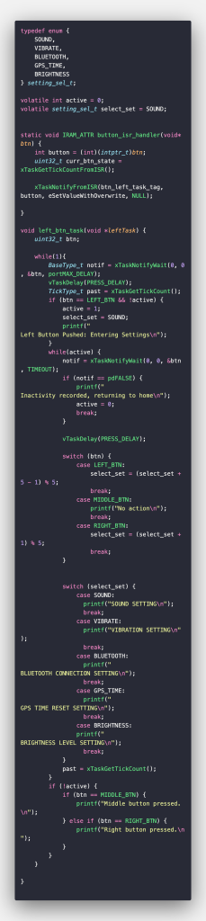
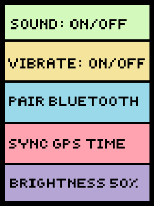
Currently, I have written code to output a message in the serial monitor representing different setting menu states, as well as button functions outside the menu (Shown below).

I am currently on schedule in terms of what I wrote for last week’s update.

In the coming week, I hope to get the button to screen functionality working in a temporary capacity until we get to the new PCB. I hope to have full functionality for the RemiGotchi firmware.


Felipe Status report 3/28

This week saw me finish the basic schedule creation page for the companion application.  Features added were the ability to save and load schedules into a text JSON.  Currently files are saved to a static location on my computer that likely would not function if the app was loaded onto another device, but that can be easily fixed with the path finder library that is already linked in the project.


With this I have enough functionality to demo the app, and while adding user control to handle mistaken inputs will b helpful in improving the user experience, that can be done after the remaining functions are implemented.  The next major task will be implementing Bluetooth connection with the device sending key schedule data over the air.  I hope to have the basic functionality complete by early next week so I can spend the rest of the time improving user functionality.

Team Status Report for 3/28/2026

This week, we finally received our PCB boards, while trying to test the PCB, we discovered that the NMOS that connects to the screen was flipped in the incorrect direction. This could lead to delays in on-screen graphics testing and will require an alternate layout for the screen while waiting for the new PCB. In the meantime, we will resolder the screen connection to the 3V pin or create a breadboard circuit to have the correct NMOS configuration.

There were no significant changes made to the design since the last report.  However, due to the long PCB assembly and delivery time, we are considering using local vendors to obtain our PCBs. Using a local vendor could dramatically increase the associated cost due to the convenience of the service, as well as possibly requiring us to assemble the board ourselves. With these factors in mind, we are still leaning towards using our previous vendor due to the additional cost and work associated with a local vendor.


Italia’s Status Report for 03/21/2026

This week, I started writing code for our PCB board to function. Currently, I am running into several issues, mainly with getting the board to function at all, which is making it difficult to test the code. The other of the issues I am experiencing is translating code from Arduino to C. Since the main testing for the platform I am using to code the firmware (PlatformIO) was originally in Arduino IDF, and I am working with ESP IDF, translating code has been difficult, in addition to the different errors the code gives.

In addition to this, I have created more graphics/sprite animations for the device.

Next week, I hope to figure out what is causing the PCB issues. This is something that should be examined earlier in the week to enable me to move forward with finishing the preliminary code. My main goal this upcoming week is to have a preliminary set of code written for RemiGotchi.

Felipe Status Report 3/21/2026

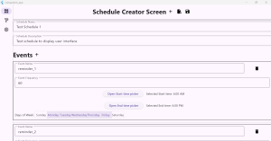
This week involved making the bare bones of the schedule creation screen, pictured below

Currently the user can use the plus shaped icon button to start the schedule creation process, and edit the created schedule setting all parameters, even being able to add and delete events.  Furthermore, input control was implemented in the event frequency parameter preventing the user from inputting strings.

Unfortunately, due to a bout of illness later in the week, I was unable to reach my goal of saving and loading schedules to and from JSON files, but that feature should be completed by Monday as it only involves loading the preexisting schedule class into a map and writing that to a JSON.


Once that step is completed, the next step will be making the UI more visually distinct and intuitive to use, as currently the shoddy alignment and dull colors do not lend themselves to the best user experience.


Overall despite the small delay I believe that I can still complete work according to the planned schedule.

Delaynie’s Status Report for 3/21/2026

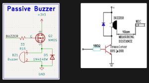
This week, I continued working on figuring out how we’re going to use Bluetooth in Remigotchi’s firmware. I built a testbench that implements BLE Serial, where you can stream bytes from one device to another once they are connected via BLE. This simplifies the firmware that we need to write by a lot. Instead of us directly manipulating GATT tables and defining our own standard of communication, we can treat it like something closer to just a serial stream. That being said, we will probably still have to handle things like our own error detection/correction and data packet structure. I also began testing our custom PCB that we received earlier this week. BLE works! I can get a serial stream to and from it via USB-C. The power seems functional enough. The charger IC gets up to 75 deg C while charging, which is mildly concerning, but potentially still within spec, so I’ll have to check on that. I tested the passive buzzer and realized that it’s unnaturally quiet. I measured the peak-to-peak voltage and eventually looked back at the datasheet and realized I wired the NMOS driver on the wrong side of the buzzer. It should be pulling the buzzer down, and the NMOS source has a stable “ground” so that the gate-source voltage is definitively 3.3V or 0V when being driven by the GPIO pin. To fix this, I’ll de-solder the buzzer from the PCB with a hot air gun, attach jumper wires to it, and use a breadboard NMOS to wire it up correctly and see if that works.  Below is a picture of what my schematic is on the left, compared to the recommended application from the datasheet on the right.

I’m a week or two behind schedule because we underestimated how long it would take for the PCB to get here. According to our original schedule, I think I would be either ordering or testing the second PCB by now. However, I still need to confirm with Italia whether or not the pinouts for the RFID reader and LCD screen work. To catch up, I’ll spend extra time next week testing the PCB.

Deliverables I want to have done next week are: working breadboard model of adjusted passive buzzer circuit, testbench firmware proving that the micro SD card slot works, testbench firmware proving that getting the time of day via GPS works, and testbench firmware proving that the RFID reader works.