This week I worked on the physical design and enclosure for our PCB and general glove design. This involved 3D printing a case which took a bit of trial and error to get just right. Based on our use case requirements, we were aiming for something that would be just a bit larger than the PCB, allow the battery to be secure, make it easy to plug things in and out of the PCB, and something that looks decent. In the first design that I printed, it was a box that looked quite bulky. I made some tweaks and printed a much nicer version with a case that says “EchoSign” as well as mounting holes and a slight curve to fit the hand a bit better. This made our design look much more sleek. We also fried one of our boards so I had to resolder headers onto another board we had and I ordered some spare parts leading up to the demo.
Ria’s Status Report for 4/20/2024
This week I worked on testing the PCB. I started by checking that the dimensions of the pins were accurate to plug the Arduino and sensors into. After noticing that the current draw for the DC DC step up motor caused the batteries to die really fast, we decided to scrap that idea and just put two 3.7V batteries in series to power the Arduino. Since we decided not to use a step up motor, I desoldered the mounting pins for that and that opened up space to mount the batteries.
I then worked on testing that haptic feedback would work on the Arduino. Somya worked on getting a signal from the computer via bluetooth that could trigger feedback. I worked on testing that the I2C circuit on the PCB with the haptic motor driver worked. I used an Adafruit example library and found that it worked fine.
I then made a 3D CAD model for a case for the PCB, batteries, and motor driver that will be secured to the glove with velcro and some adhesive on the back of the hand. I plan on finalizing this look by the end of next week.
Ria’s Status Report for 4/6/2024
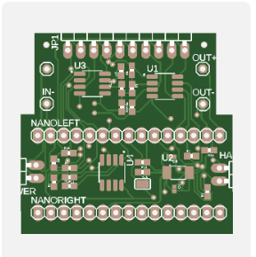
This week I worked on finalizing the PCB, creating the documents to submit the order (bill of materials as well as file detailing part placement). I am in contact with the vendor and we will hopefully get our PCB delivered very soon with no issues. I followed best practices when creating this design, an image of it is below. The PCB will be appx. 1.5″x1.5″.
This week I also worked on testing the calibration program I wrote that will gather data on a user’s max and min flex amount and map their flex value to the range from their own min to max. This will allow the glove to work for people who flex different amounts. We will use this feature for our double glove design.
Finally, I worked on battery supply. I decided that getting a compact battery was best, so I got a 500 mAh LiPo battery that supplies 3.7 V. I got a small DC to DC step up converter to give us a voltage value comfortably within 4.5V-21V which is the Vin range for the Arduino Nano BLE Sense Rev2.
Ria’s Status Report for 3/30
This week, I started by deciding if the speaker was a feasible endeavor for our team. Ricky mentioned a library called Talkie that does text to speech on an Arduino. I thought about how we can use that library on the glove and output speech through a speaker after sending that audio data through an amplifier circuit that I built. Unforuntately, when trying to run the test script I wrote, I found that Talkie does not support the BLE board we have. I assumed since the BLE board has the same architecture as the other boards Talkie does support, it would be worth testing it out, but the source code cases on the board in use and BLE was not on that list. Instead of modifying the source code for the library, we decided that for MVP, it was the best use of our time to keep the speech output coming from the computer.
My next task for this week was figuring out how to power the board. The LiPo 3.7V batteries are the ideal size for our portable product, but the BLE board takes in 4.5V-21V into Vin. I thought about if a larger bulkier battery could work but could not find a battery that was both cheap and was lightweight enought to be mounted on a wearable device. I decided to look into a step up dc dc converter instead. The capacitors on them are a bit bulky, but they will do the trick and the MT3608 chip can output a voltage in the range we need. I found the schematic for this board, added it to our custom pcb, ordered the part, and plan to test the wireless powering of our board on Monday.
Ria’s Status Report for 3/23/2024
This week I focused on creating the PCB layout for our circuit thus far. I started off by drafting the circuit with each flex sensor and op amp. Then we had to finalize which board we are using which we did altogether (determining if Bluetooth would meet our latency needs). We finally decided to stick with the Arduino Nano BLE Sense Rev2 and I added in those headers into the schematic. Finally, I added headers for a battery, and headers for the speaker and haptic motor.
The next thing I did this week was solder five more flex sensors to red white wire pairs so that they can be ready to attach to the second glove. Now that our first glove works, we decided to parallelize the tasks needed to be done to duplicate it. The next thing I’ll focus on for the following week is getting the speaker and haptic motor driver to work on one glove.
Ria’s Status Report for 3/16/2024
This week my main task was to assemble the circuit that would maximize the voltage range output for the flex sensors. We faced the issue where we wanted to use a full 5V range by supplying 5V to each flex sensor, having its voltage output go through an opAmp, and maximizing the range output. The issue we found was that the Arduino Nano BLE Sense Rev2 may be able to supply ~5V (through the computer via USB), but it first of all ranges between 4.5-5.5V and the analog input pins cannot read more than 3.3V because the operating voltage for the Nano is 3.3V. This is an inherent characteristic of the Arduino Nano which is why we cannot reach the full 5V range and we will have to maximize the range to 3.3V. By creating a simple circuit with an operational amplifier, we managed to get a range of 0-2.8V to ensure we don’t max out the ADC. We realistically don’t get near 0 V but getting as close to it as possible diversifies our input as much as possible to give our ML model a good chance at classifying well. We used a simple non inverting amplifier to implement this.
I also soldered wires to our flex sensors to make it easy to connect them to our breadboard. I also cleaned up the circuit we initially made to prevent shorting any connections and making it easier to debug. I also wrote the Arduino script to receive data from the flex sensors and IMU as we were assembling the glove.
Ria’s Status Report 3/9/2024
I spent the majority of my time at the beginning of the week preparing and delivering the design review presentation. This was pretty stressful and I think there are a lot of things I would do differently, but it was fun to do a presentation like that for the first time.
My next main task for this period was to make sure we were receiving data from our IMU and formatting that data to look like what we wanted it to feed into our ML model and concatenate with the flex sensor readings. I found that the acceleration readings were a pretty all-encompassing way to capture orientation data. As explained in the previous report, adding up the components in the x, y, and z directions gives us the downward g force, so the breaking down of those components tells us exactly what angle our hand is at. I decided to quantize that data to the nearest .5 to simplify readings but also provide detailed measurements without potential model overfitting.
Week of 2/18/2024
This week I focused on finalizing the design for our software interfacing and ordering parts.
I made an observation that Bluetooth may not satisfy our latency requirements which Ricky helped confirm based on a past project failing to incorporate Bluetooth for this reason. This is why I proposed using WiFi instead. Because we have BLE built into our board, we realized that we would need a different board preferably with a built in IMU with a triaxial accelerometer. We found the Arduino 33 Nano IoT which satisfied all of our requirements but it had less compute power. We value compute power so we decided to start with the Sense board and switch to this if it does not work out so we ordered both.
The next thing I did was write some code to connect to the board and retrieve data as well as format that data. I wrote it for the local and remote hosts. We still have to test this since we don’t have our boards yet.
Ria’s Status Report for 2/17/2024
I spent majority of this week ironing out the design review slides and its content trying to weigh all pros and cons of every decision we made and making sure we didn’t leave any major loopholes.
The first thing I focused on was the board we are using. Our current communication protocol called for bluetooth but since Gesture Glove found that bluetooth resulted in them not meeting timing requirements, we thought the IoT Nano board might be a good option – but it has less compute. Since we are more concerned with functionality first, we will make an iteration with the BLE Sense board then switch to IoT when we get to wireless communication.
I also tried to spend ample time on breaking down each subtask into smaller subtasks as much as possible. This was a joint effort with my team mates which involved creating more action items for our schedule and refining the block diagram as well as creating a data flow chart.
Ria’s Status Report for 2/10/2024
I spent this week doing a ton of research on what compute to use for our design as well as some lower level ideas for the software implementation. These were all things I presented in the team meetings so that we could further our design into a more complete product.
I first looked at the macro level of the project and found gloves that we could iterate on. I found some very basic ones on amazon that were cotton and we decided to use those for now.
Then I researched a few designs for how the compute would be set up. The full fleshed idea would ideally have two boards, one on each hand doing all compute and all interactions with the world. But since this is a really complex design, we decided to break our project up into rapid prototypes with the first one being a single working glove communicating to a computer via bluetooth. Thinking through the processes involved and breaking down the problem into subcomponents helped me better visualize the future of the class and product.
I proposed a few boards: Jetson Nano, Arduino Nano 33, and the Pi Zero. With the information each of us provided to the conversations helped us prepare for next week when we do finalize a design.