
What did you personally accomplish this week on the project? Give files or photos that demonstrate your progress. Prove to the reader that you put sufficient effort into the project over the course of the week (12+ hours).
I finished the circuit diagram for the sensor wiring (with two sensors displayed as opposed to five for ease of looking at); this schematic is one that I will keep adding to/modifying as our design needs change. 
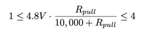
In addition, I did the mathematical calculations for determining the options for what resistor we want to use in series with each flex sensor. This is quite important to get right because one of the biggest challenges we anticipate after looking at Gesture Glove’s challenges/advice from our TA is flex sensor sensitivity. To address this, we need an output range of values as wide as possible, so if someone signs an ‘a’ versus a ‘b’ the voltage outputs aren’t something like “1.200V” and “1.215V”. As such, we decided that our ideal voltage range would be 1V-4V. This creates the below inequality:
The tricky thing is about having a variable resistor (i.e. the flex sensor), is that the value that satisfies the two equations that can be formed from the above inequality is negative. So, the best thing you can do in practice is form a range of resistor values and play around with multiple resistors within that range to see which ones produce the widest output range. Through my calculations, I found this range to be ![]() . As such, I tested five of the most common resistor values within this range: 2.7kΩ, 3.3kΩ, 4.7kΩ, 10kΩ, and 47kΩ. Of course we will test these in the actual breadboard circuit, but I also manually tested them and found that the range reaches maximum of ~0.8V with ~10kΩ of resistance, which isn’t great. So it’s looking like we will need to use an op-amp. I looked at Spectra Symbol’s data sheet, which listed LM358 or LM324 op-amps as suggested. Below is what the circuit diagram for that would look like:
. As such, I tested five of the most common resistor values within this range: 2.7kΩ, 3.3kΩ, 4.7kΩ, 10kΩ, and 47kΩ. Of course we will test these in the actual breadboard circuit, but I also manually tested them and found that the range reaches maximum of ~0.8V with ~10kΩ of resistance, which isn’t great. So it’s looking like we will need to use an op-amp. I looked at Spectra Symbol’s data sheet, which listed LM358 or LM324 op-amps as suggested. Below is what the circuit diagram for that would look like:  . Lastly, I finished all my tasked sections for the Design Report that was due last Friday.
Is your progress on schedule or behind? If you are behind, what actions will be taken to catch up to the project schedule?
My progress is on schedule.
What deliverables do you hope to complete in the next week?
Now that all of our parts have arrived, I hope to accomplish two tasks in particular. First, I want to do some flex sensor unit testing by building a simple voltage divider circuit and seeing which of the five selected pull-down resistors will give the widest range of V_out. I want to do these units test first so that way if further sensitivity is required by way of an op-amp, I know that before launching into building the entire circuit to accommodate the five flex sensors. Second, after I’ve determined the pull-down resistor through educated trial and error, I would like to have the five flex sensor circuit built by Wednesday. That way we can get to checking if the Arduino code for reading out from the sensors works, and possibly even start the data collection process this week. All our moving parts in preparation for the model training are really close to being done, so hopefully the time we’ve spent preparing everything pays off and data collection goes smoothly. I also want to bring up making a PCB board with the team on Monday’s meeting.