Team Status Report for 3/30

Currently, the greatest risk is that we will not be able to extract usable data from the microphones. If this is because the microphone doesn’t react to any sound input as proven on the oscilloscope (likely incorrectly soldered), we can repeat the assembly/soldering process with more components. If the microphone reacts to oscilloscope testing but not to the microphone testing program that prints to the serial monitor, further microphone testing is required to determine the source of the issue. If the microphone reacts to environment sound but the data we receive does not directly correspond to what we expect, we need to continue signal processing to calibrate the data.

We need to have the hardware aspects mostly complete by Tuesday (the first music testing session of the week) and the webapp subsystem mostly complete by Wednesday (interim demo day).

Since last time, we tested the microphones and LEDs on each board to find out which boards have which functioning. We also tested a program that would change the LED color if the microphone input exceeded a certain threshold. Webapp research about the database and file format continues. Also, we now have a decibel meter! This will provide a baseline against which we can measure the bracelet results.

We haven’t changed the design of the system.

The Gantt chart has been updated:

  • The interim demo is now scheduled for Wednesday, April 3rd.
  • Database, visualization, customization is due Friday, April 6th.
  • Timeliness/accuracy/heat tests are also due April 6th.

Clapping demo

Caption: The lights change color to red and back to yellow very fast, so if you want to see it better, change the video speed to 0.25, and focus on 0:02 to 0:04.

Also available on YouTube: https://youtube.com/shorts/fKVRntFnD_Q

Freda’s Status Report for 3/30

What did you personally accomplish this week on the project? Give files or photos that demonstrate your progress. Prove to the reader that you put sufficient effort into the project over the course of the week (12+ hours)

I solved a few problems mentioned in the previous status report.

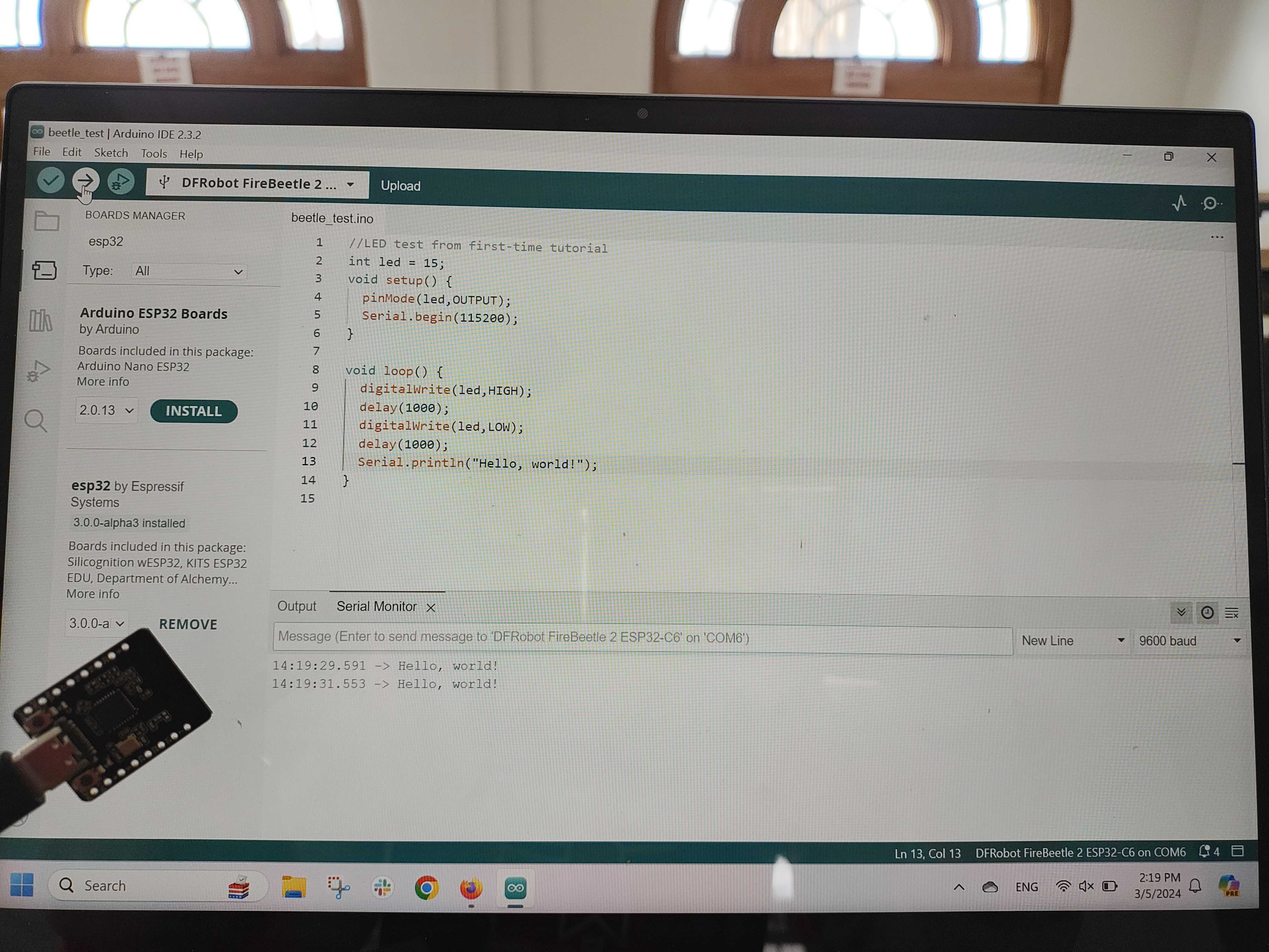
  1. Nothing prints in the Serial Monitor: in Arduino, go to Tools -> USB CDC On Boot “Enabled”. If “Disabled”, nothing prints.
  2. Beetle connection isn’t recognized/won’t upload code: often, when I switch out a Beetle and/or data cable (we have 2 of each), the upload process will fail. Sometimes it fails because the port is grayed out and won’t allow you to connect, or sometimes it’ll say some Serial data error. Here are solutions I do to fix this:
    • Unplug/replug Beetle, restart Arduino/computer
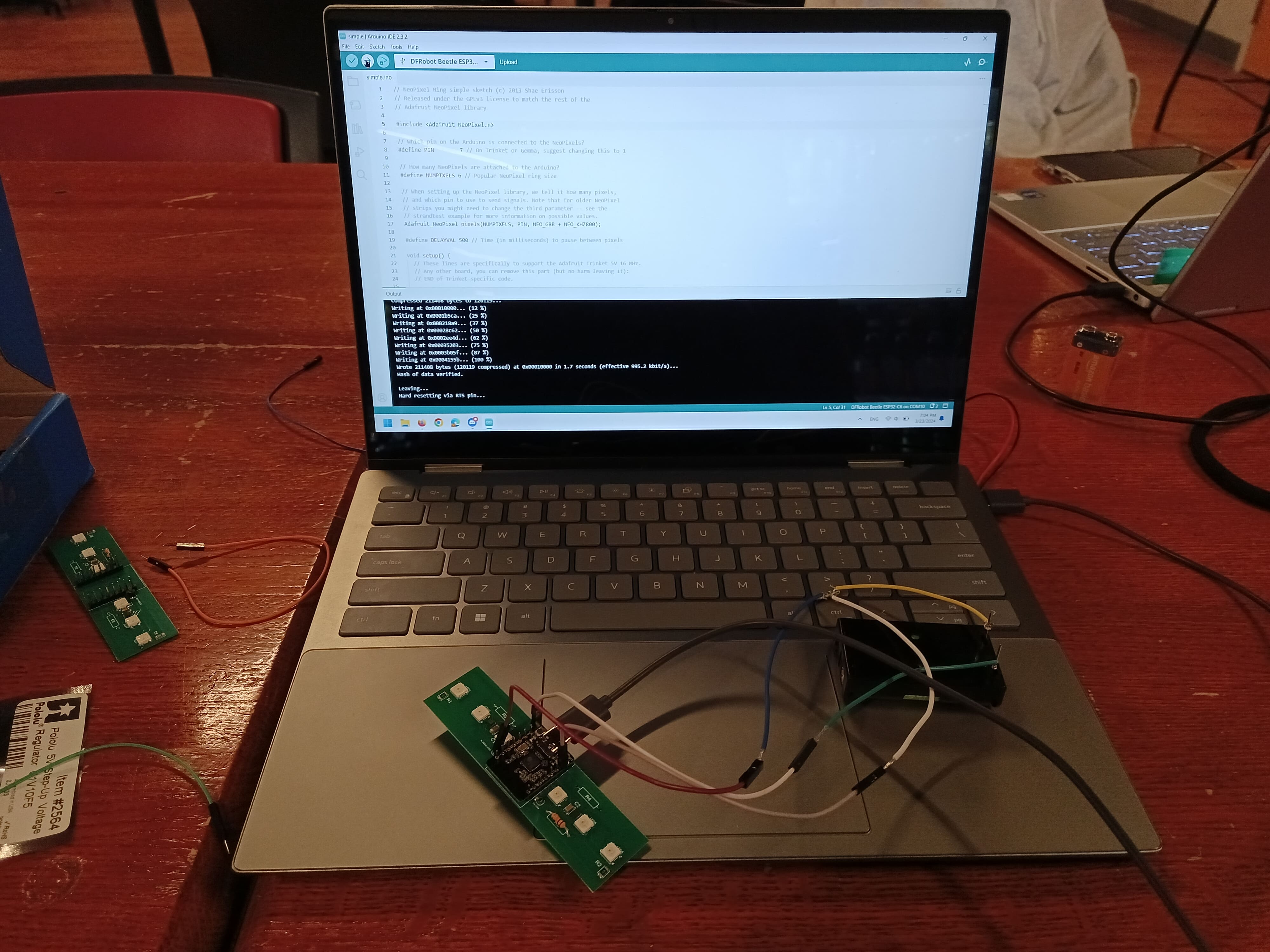
    • Spam the Beetle buttons for boot/reset during compilation. You should hear the USB connect/disconnect sounds if your computer has those. It might not work the first time, but eventually you get the timing right and it’ll finally agree to upload. I usually do the blink test for this, since it’s pretty easy to tell if it worked. If the Arduino IDE says “upload successful”, but you still don’t see any light, click the reset button once (right button), and then the light should start blinking.
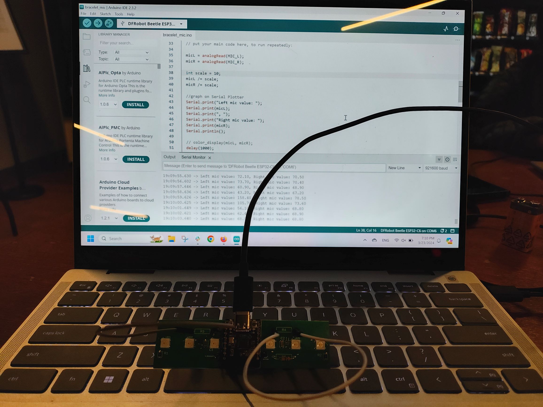
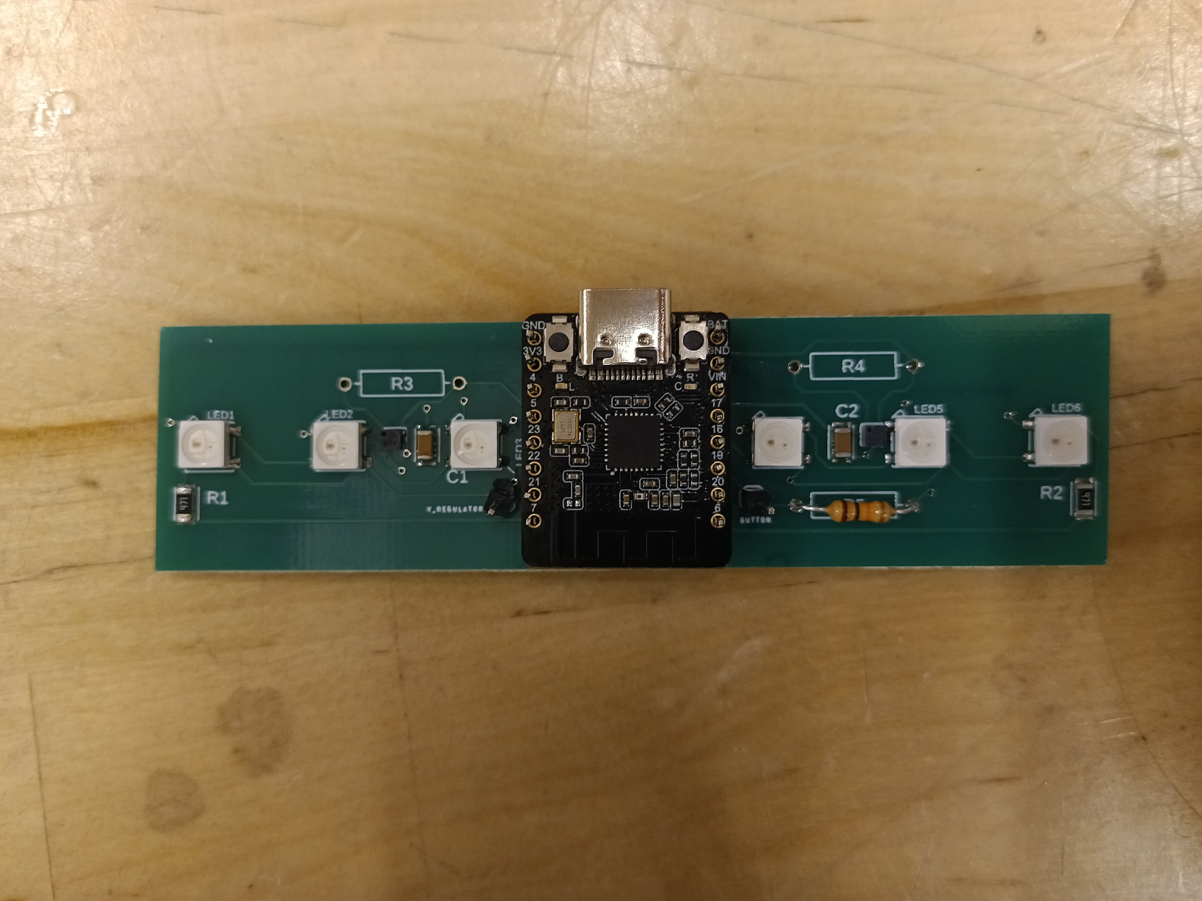
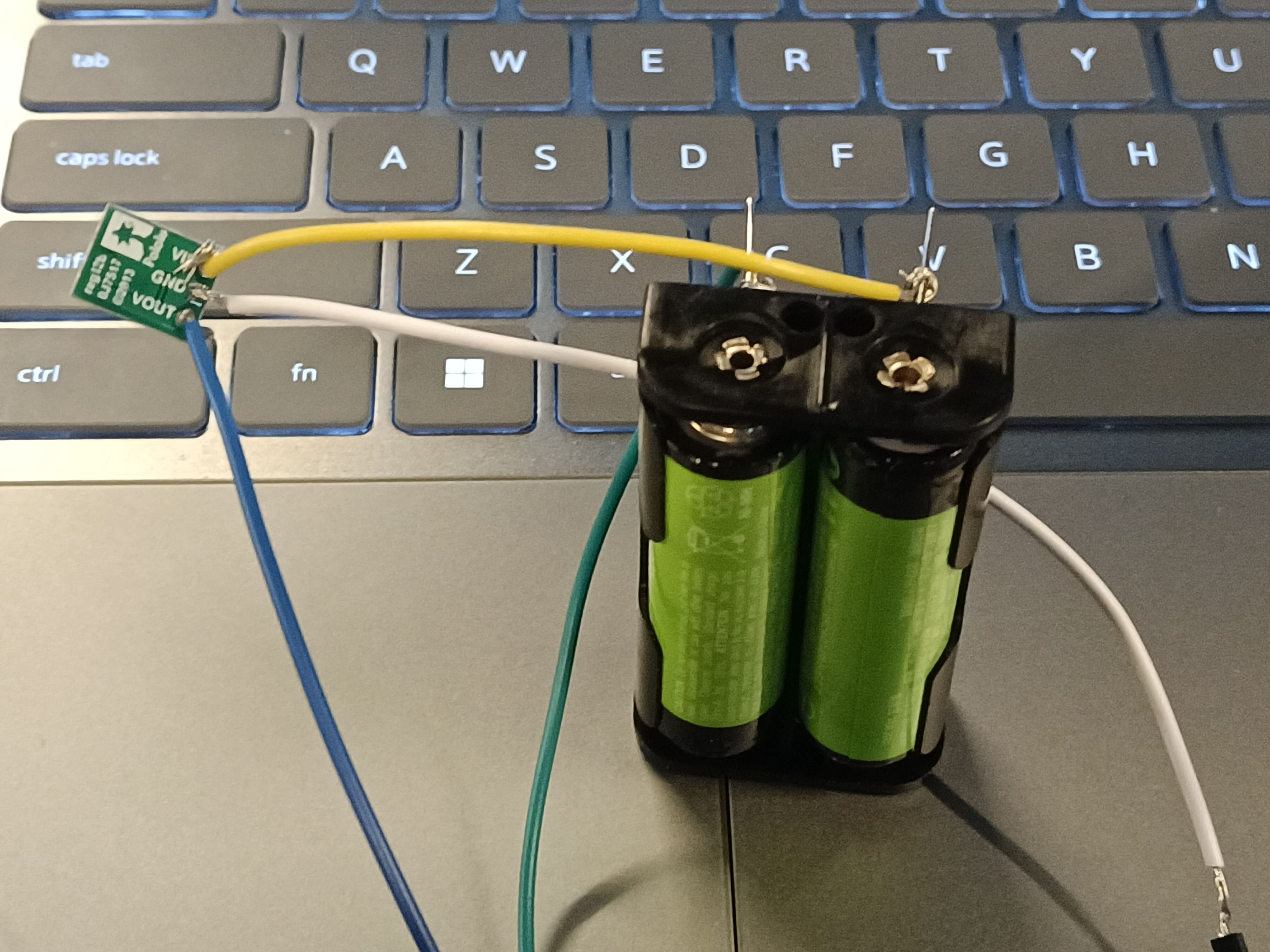
  3. Lights not lighting up: at first we thought it was the Polulu boost converter not boosting our voltage to 5V correctly, because we triple checked all our connections and they looked correct. So the next solution was to find a 5V supply directly and skip the Polulu middle-man. Techspark has some of those, so after connecting the Beetle to common ground, as soon as the 5V probe touched the V_regulator pin I set up, we were treated to a glorious array of wonderful colors! They were bright and rainbow and all we could’ve ever hoped for!*

*We actually were hoping that all the boards would have working lights, but when we tested boards 3 and 4, there was no reaction from applying the 5V. It’s pretty strange, since the Neopixels are bigger and thus easier to place and solder correctly compared to the mics. We also placed all the Neopixels in the same orientation, so wrong connections shouldn’t be an issue. Our success rate for lights is 3 out of 5 boards, so 60%.

Turns out, it was just a poor connection issue with the Polulu, because if you press on the boost converter at a certain angle, the lights will turn on. We also transferred all our wiring to header pins/breadboard connections to be more stable instead of just floating around. We will be soldering it on for the final product, so that won’t be an issue. We’re just hesitant to solder things on now because things aren’t finalized and soldering is a pain to undo.

Light video

After that, we tested all the mics with Prof Fedder’s tutelage. He explained that the mics DC voltage was around half of our power supply of 3.3V (so about 1.1V). So we first use the oscilloscope to measure our mic output pins to see if we get anywhere in that range. (Unfortunately, we can’t check the mic pins directly because they’re SMD, and thus directly under the mic.) Once we have a confirmed reasonable voltage (the bad mics register voltage levels in the mV), we move on to AC voltage. The test here is to play a tone near the mic and test different distances: we should see the amplitude of the sine wave on the oscilloscope change accordingly. For the non-working mics, we just saw “noise”.

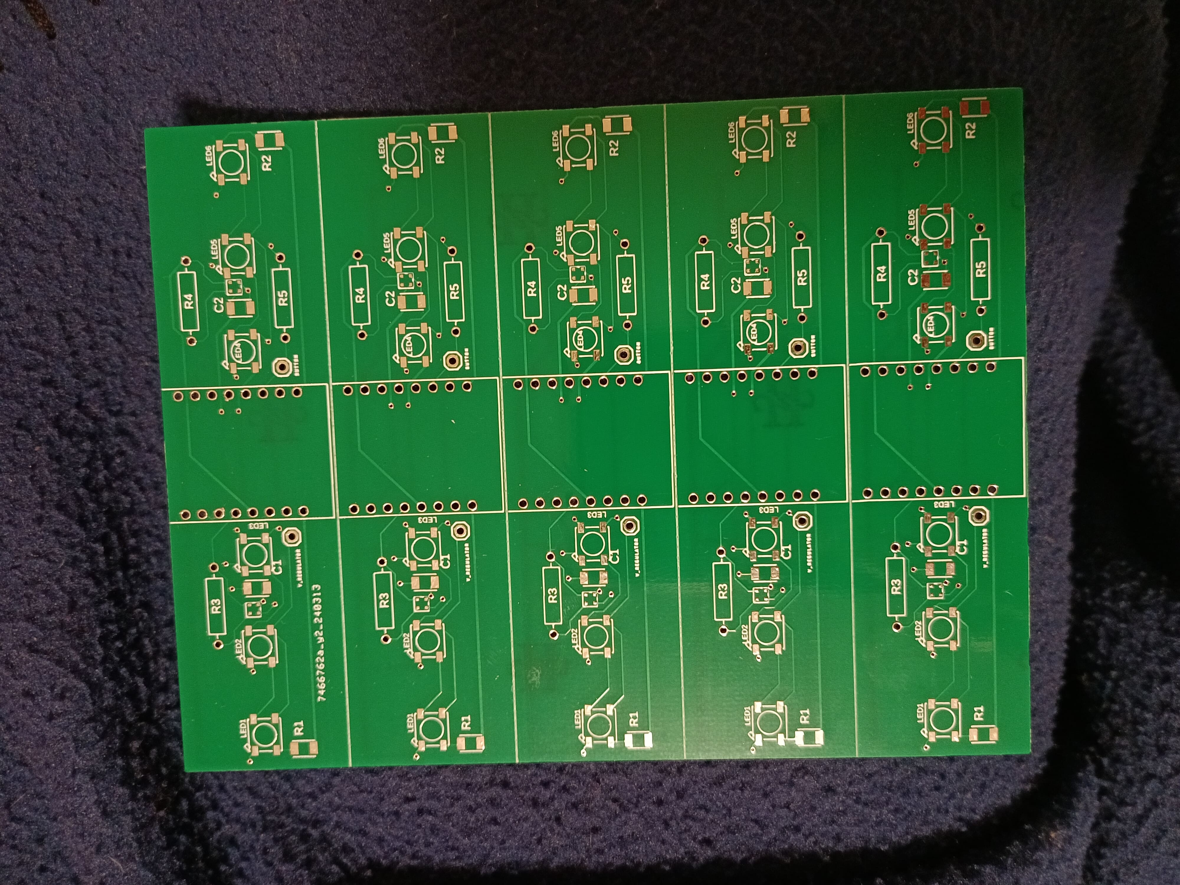
Since the mics are so tiny, it’s very hard to apply solder on them to balance between falling off from not enough solder, or shorting all the connections because the solder reflow was too much. During the PCB assembly, we tried 2 methods; on the left side (mostly likely) of each board, Lucy applied a bit of extra solder manually to help the mics stick better. On the right side, I set the mics with just the initial amount of solder that made it through the solder mask. Here are the results for the boards’ mics that made the cut.

1: both mics work

2: right mic only

3: right mic only

4: left mic only

5: neither

It looks like the right mic technique may have had a bit of a slight advantage over the left mic, but honestly since the sample size is so small I’m not sure we can derive statistical significance from this. The survival rate of mics is 50%, but if we want both mics to work, the survival rate drops to 20%.

Since LED survival rate is 60%, the overall board success rate would be 30% if optimistic, and 12% if not optimistic (multiplying the survival rates because “and” condition). So optimistically we’ll need to build 4 boards, and non optimistically, 10 (expected value math). Then we apply backup calculations by doubling these amounts to get 8 or 20 boards. They will probably all cost the same amount so it’s not much of a cost thing as it is more of a “we need to make sure we have enough of the other components”. For example, our LEDs deplete the fastest since there’s 6 per board. We used up 30 of them for the prototype boards, so we have 70 left in our pack. If we are optimistic, we would have enough if we built 8 boards, but not enough if we want to build 20 boards. Prof Fedder gave us more microphones and says he has many more, so that probably won’t be our limiting factor. We also grabbed a bunch of the SMD resistors and capacitors, and only use like, 2 per board so we should be good there too.

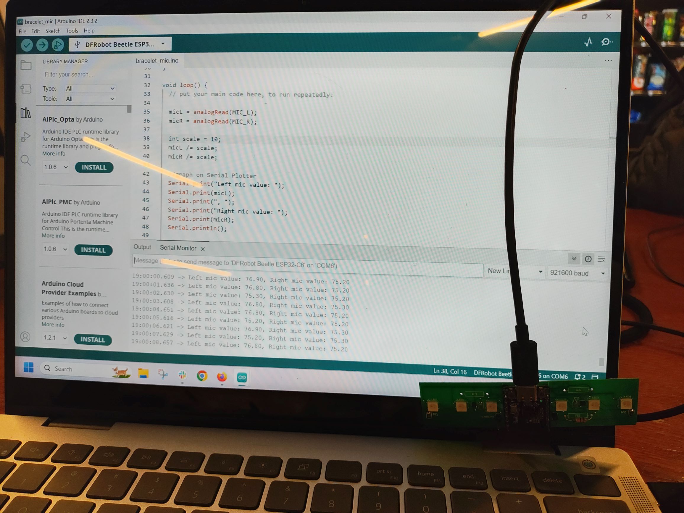
Then was the music recording session where, for the first time, we had both the professional decibel meter and our own DIY mics (uncalibrated). Hopefully, we would see some trends between them so we could have an idea of what kind of math is needed to calibrate our mics. I used board 1, since we established that both mics were supposed to work, and put the decibel meter and board right next to each other on the music stand in the middle between the piano and singer. Observations:

  • FAST, Lo, dbA settings: during ambient noise, it’s pretty close (both in the 40’s), but when music starts, the professional mic picks up the noise way better than the board mics; think i spotted around 60 on the board mic when I moved it closer, which is still less than the 70s to 80s that the decibel meter says.
  • FAST, Hi, dbC settings: ambient now around 60 on the decibel meter instead of 40, and music is around 80s to 90s. Board values still stay around the same range as last time though.
  • Something a bit concerning: the left mic seems to be more sensitive and goes up to 60, but the right mic stays solidly at 48-49 the whole time, even though both of them are supposed to work and I assumed they’d be around the same sensitivity level? They have the same resistors at least. The left mic is closer to the singer, the right mic is closer to the piano, but that shouldn’t make that much of a difference? Maybe the decibel meter mic was nearer to the right mic which may affect things.

The code was sampling with delays at this point so we’d know the sampling frequency exactly. Later we just got rid of the delay to sample as fast as possible, and based on the timestamped CSV logs, it calculated about 1200 readings per second, which is abysmally slow compared to the range that singers and pianists use. So perhaps that’s why the mic readings were suffering from such a limited range/sensitivity during the music session. Katherine can tell you more about her plans for fixing this in her section.

Is your progress on schedule or behind? If you are behind, what actions will be taken to catch up to the project schedule?

Amazingly, I have actually finished all my tasks on time for once! I also have code that changes the color of lights based on mic readings. Since the mics are uncalibrated, the thresholds are bogus, but as a proof of concept, you can see the video in the team report where clapping changed the light color from yellow to red. We could add gradient colors to interpolate smoothly between the yellow and red (orange) through HSV conversions to show the user more precision in the readings instead of just “buckets”, but when we were testing, we noticed the lights were sometimes flashing between yellow and red so quickly that it looked orange already due to persistence of vision, so perhaps gradient is unnecessary and we can keep the code simple.

What deliverables do you hope to complete in the next week?

I can try physical fabrication of the bracelet with the hard PCB, just to have some practice. Perhaps I’ll run into surprise issues that I didn’t know were going to be a thing. In particular, since our plastic sheet got lost to the void, we only have plastic tubing right now, so I can experiment with how viable of an option that is or if we really need the plastic sheet instead. We can also test how much the mics are affected by being in plastic; although depending on how noisy the uncalibrated data is, I’m not sure if we’ll be able to derive meaningful results if testing uncalibrated.

Katherine’s Status Report for 3/23

This week, I wrote and tested out a program that relates microphone input values to dB values (multiplying/dividing input by a constant) on the PCB. I can get a Serial Monitor reading of the left and right microphone values that has approximately the right magnitude when the input from each microphone is scaled down by 10.

Unexpectedly, using no resistor (open) in the spaces meant for the gain resistor on the analog microphones returns reasonable values. The values returned are on the order of the values for minimal resistance (when the space for the gain resistor is occupied by a wire).

This photo shows sample results from the microphones without any resistor.

This photo shows sample results from the microphones when they have a gain connection of minimal resistance (wire).

Progress was technically behind on microphone signal processing, the Bluetooth-webapp connection, and visualization of decibel readings. Microphone signal processing is now expected to be complete by this Friday. Bluetooth is most relevant to webapp-device integration, and can be addressed after the interim demo. However, it might be useful to continue searching for resources/information if other tasks are completed early. Visualization of decibel readings is expected to be complete before March 30th.

Bluetooth research proceeded. I attempted to go through the steps of the Bluno basic demo (https://wiki.dfrobot.com/Bluno_Beetle_SKU_DFR0339, https://wiki.dfrobot.com/Bluno_SKU_DFR0267#Bluno_Basic_Demo, troubleshooting information https://wiki.dfrobot.com/Bluno_SKU_DFR0267#target_7, https://support.arduino.cc/hc/en-us/articles/6554914611228-Compilation-error-exit-status-1), under the assumption that it would be fairly similar to the Beetle’s BLE system. I was unsuccessful. However, I was able to install the APK on my phone and look at the names of Bluetooth devices in the area (resources: ttps://www.lifewire.com/install-apk-on-android-4177185, https://www.softwaretestinghelp.com/how-to-open-apk-file/, https://support.google.com/googleplay/thread/56676897/how-do-i-install-3rd-party-apps-and-apk-files-on-my-motorola-g-stylus?hl=en). I looked at these resources (https://www.arduino.cc/reference/en/libraries/arduinoble/, https://www.arduino.cc/reference/en/language/functions/communication/serial/println/) when trying to debug the code; it printed an error reading “controller lib commit: [77d09ce]”. This error apparently stems from a conflict between the ESP32-C6 module and the main controller module (https://github.com/h2zero/NimBLE-Arduino/issues/645). It seems like we would have to change how the Bluetooth module and the Beetle interact with each other in order to fix this problem.

Most of my tasks this week will focus on microphone signal processing. I’m going to tune the scale that determines output values: gather microphone data from an established sound, measure the sound dB externally, and improve the microphone results by adjusting the scale value to better match the external measurement (thank you, Freda, for suggesting this experiment). I would also like to graph some portion of these results (both from the external measurements and the microphones’ measurements).

For Friday, I intend to update the microphone signal processing code to:

Take multiple samples per second and average or otherwise combine them in order to account for external noise not relevant to the user (for example, tapping the device near a microphone location).

Use an FFT (https://en.wikipedia.org/wiki/Fast_Fourier_transform) like https://projecthub.arduino.cc/abhilashpatel121/easyfft-fast-fourier-transform-fft-for-arduino-03724d to define dB value as based on the highest amplitude of the highest relevant frequency in the microphone input, and use Serial Plotter to visualize the frequency results.

This week, I also intend to participate in timeliness, accuracy, and heat tests for the hardware components of the bracelet.

Team Status Report for 3/23

This week, we received and put together the PCB prototypes, started code for the bracelet, and worked on the webapp.

  • What are the most significant risks that could jeopardize the success of the project? How are these risks being managed? What contingency plans are ready?

One risk is that the plastic wrap still hasn’t come in, so the interim demo bracelet might need to be fabricated entirely out of plastic tubing or have no plastic covering. The casing isn’t a major subsystem, so we should be fine without casing for the interim demo anyways. BLE setup/interfacing is also challenging, but will be addressed after the interim demo when integrating the bracelet and web app.

  • Were any changes made to the existing design of the system (requirements, block diagram, system spec, etc)? Why was this change necessary, what costs does the change incur, and how will these costs be mitigated going forward?

No changes were made to the existing design of the system. Soon after the interim demo, we may consider changing requirements or other design elements if feedback suggests that it would benefit the system.

  • Provide an updated schedule if changes have occurred.

The Gantt chart has been updated to reflect that complete (separate) subsystems of the physical bracelet and webapp are due April 1st (interim demo).

  • This is also the place to put some photos of your progress or to brag about a component you got working.

Isn’t it beautiful? Let’s hope it actually works.

Freda’s Status Report for 3/23

The PCBs finally came in this week, so Lucy and I were able to assemble them in the PCB lab and hand solder on the rest.

A few takeaways: because everything is so small, the solder mask took a while to line up precisely, and we weren’t sure if there would be enough solder on the smallest component (microphones) to stick, but luckily it did. Another thing that was tricky was looking closely at the mics and LEDs since those have directionality in placing them. We are relatively sure we got the mics oriented correctly at least, since Katherine was able to get reasonable readings. LEDs deserve their own section later. Finally, we need to make sure not to run out of the SMD components like capacitors and resistors (took a bunch just in case), because apparently they’re not kept stocked and we’d have to order them, which causes delays. We could cut apart the PCB into each panel using scissors since it was thin and came with perforated marks.

Highlights of hand soldering include using tape to line up the headers relatively straight so the beetle will be able to fit properly. The single headers don’t have to be that straight because we were planning on wiring those connections.

I could now get started on trying to get the LEDs to work. At first, I tried to use the FastLED library since that’s what a bunch of example Neopixel projects on Adafruit’s website used. Unfortunately it led to a bunch of internal errors within the library itself, and everytime I fixed one, a new error would pop up. It was like playing whack-a-mole, except hitting things with a hammer would probably not solve the problem.

Next I tried the Adafruit Neopixel library since that was mentioned on the Neopixel page. That compiled fine, but then nothing happened. We tried checking the pins, debugging with print statements (nothing printed, not even in the setup() before any real code was run). Admittedly, our setup may not have been the most stable since we didn’t solder the battery/boost converter stuff yet (couldn’t find any solid core wires, which would’ve been more helpful), but I don’t think that should be the issue. In addition, we are relatively sure all of them are oriented correctly after consulting a pin out of the component online.

In other news, an ongoing conundrum has been how accurate our phones are for measuring dB. Previous data showed that each phone was relatively precise (Katherine consistently got the lowest readings and Lucy the highest), but I volunteered as tribute to formalize our findings with fun things such as box plots and outlier analysis and standard deviation!

For our recording session with the music students, we tried different variables to see how sensitive the mics are and how much specific placement really matters. Specifically, we tried trials where we lined up the phones in different orders, and for the last trial, we placed the phones as far away as possible (other side of the room).

Conclusions:

  • no outliers, even with the very far away trial; it does skew the data ofc, and the box plots look more symmetrical without it
    • mostly avg and max was affected by this ^
    • std dev calculations not really affected, since everyone should be affected in about the same way
    • katherine’s avg didn’t change without the last trial because the last trial didn’t have the lowest value XD
  • Lucy’s phone seemed most sensitive (largest drop) to being farther away
  • Everyone’s std dev were within 2 db if ignoring the last trial

I didn’t expect the light debugging to be so difficult, especially since there’s a bunch of straightforward example code to try. That was supposed to be done by the end of this week, but I’ll try to have it done by Friday’s recording session instead, and perhaps we should meet with prof to ask for help.

Katherine’s Status Report for 3/16

To correct an error from last week: this week, I was supposed to be working on microphone signal processing, not LED signal setup, in addition to electronic prototyping.

In our weekly check-in discussion, I got an idea of how microphone signal processing is going to work in the context of our project. My eventual plan to determine the necessary sampling frequency is to test the bracelet microphones by sampling at the higher rate (including all expected overtones) when at a music practice. I hypothesize that the overtone frequencies will tend to be softer/have smaller amplitudes, which will reduce the frequency range we would have to work with and therefore our required sampling speed as well.

Some of my progress is on schedule, while other parts are behind.

The on-schedule elements are as follows. I wrote the logic for the ratio of microphone decibel values affecting the color of each LED when in directionality mode. When in directionality mode, the LEDs light according to a dB value that is a weighted average of the dB value for either direction (the weights differ depending on the LED’s location relative to either microphone). The farthest and second-closest LEDs from the Beetle on each side will display the color value corresponding to their side’s microphone input, while the LEDs closest to the Beetle will display a color value corresponding to ⅔ of their side’s microphone value added to ⅓ of the other side’s microphone value. When not in directionality mode, all LEDs will display a color corresponding to the average of the two microphone input amplitudes. The logic for determining direction already exists (I believe last week’s “how determining direction… will work” was in the context of LED colors?). For the record, it takes the ratio of the amplitude from each microphone input and assumes that a sound equidistant from each mic will have a 1:1 L:R ratio, while a sound completely from the left or right will have a ratio of X:1 or 1:X (X being the maximum ratio). It then scales based on the ratio of input amplitudes to find an angle value between these. X will be iterated on during directionality testing.

I am behind on establishing the Beetle-Bluetooth connection. According to https://github.com/espressif/esp-idf/issues/6550, in order to establish a connection to my phone with the correct security, I need to turn on secure simple pairing or change the mode to mixed mode; I need to research if it is recommended to change these features of the Beetle’s Bluetooth module. Further research suggests that it would be useful to connect to the Beetle through a third-party app (https://wiki.dfrobot.com/DFRobot_Bluetooth_4.1__BLE__User_Guide#target_2 states that it is required for Bluetooth 4.1, and our Beetle uses Bluetooth 5), but none of the apps I tried could recognize the Beetle.

Tasks that depend on having the PCB are also behind. The PCB is scheduled to arrive on Tuesday. Once the PCB is assembled, I plan to continue work on electronic prototyping (including researching the Beetle-Bluetooth issue) and microphone signal processing. I will also help with testing the webapp if necessary and with visualizing decibel readings if time permits.

Freda’s Status Report for 3/16

What did you personally accomplish this week on the project? Give files or photos that demonstrate your progress. Prove to the reader that you put sufficient effort into the project over the course of the week (12+ hours).

In the previous status report, I assumed that the PCB would be at least delivered so we could at least check it out, but unfortunately that’s actually scheduled for next Tuesday. Thus, a lot of material items that I also wanted to do, such as assembling the PCB, trying out the LEDs…etc., were blocked. On the bright side, I was able to successfully set up my Arduino environment to connect with the Beetle (on-board LED blinking “Hello World” worked).

In the meantime, I’ve been working on compiling different projects’ uses of Neopixels (Adafruit has been particularly helpful). I don’t expect to be able to copy-paste code, of course, but being able to tweak existing code that I know is supposed to work should be easier to get working than writing from scratch. In addition, the multiple examples will help me understand the mandatory vs customizable components of the code. Here are the links I’ve been looking at:

Is your progress on schedule or behind? If you are behind, what actions will be taken to catch up to the project schedule?

Because we thought we’d have our PCB in this week instead of next week, all of the PCB assembly and testing of components had to be pushed as well. Our goal is to rapidly assemble the PCBs (ideally within a day or two of receiving them, depending on our schedule availability) so we can get to the coding, since I suspect we’ll probably run into errors there.

What deliverables do you hope to complete in the next week?

Since the PCB is expected to be in by then, I hope to be able to assemble all the components in the PCB lab, read up on the FastLED library that a bunch of the above projects used, and try some of their simple example code to make sure the PCB passes before trying to upload more complex code.

Katherine’s Status Report for 3/9

Over the past 2 weeks, I participated in completing the design report, ordered the PCB from JLCPCB (it should arrive in 4-6 business days), and completed the first-time use tutorial on the DFRobot Wiki for using the Beetle to display “Hello, world!”.

A Beetle with USB connection is held in front of a screen displaying the Arduino IDE, where the Serial Monitor reads "Hello, world!" twice.

I also realized that the circuit diagram I created for the design report did not mention its sources; it was compiled based on diagrams from the AKU1126 acoustic microphone datasheet, Beetle pin diagram/definition, NeoPixel (SKC6812RV) datasheet, and Pololu boost converter description.

Here is a sketch of the bracelet that was not included in the design report.

Front and top views of the bracelet. The PCB has the Beetle in the center, with the boost converter on top of it. On each side of the Beetle is a line of 3 LEDs and a microphone, evenly spaced with the microphone between the first and second LED. The PCB is on the top layer of the bracelet, and the battery is behind it when viewed/beneath it when worn. All electronic components are covered in plastic insulation. String at each end of the insulation is fed into a cord lock.

All deliverables from last week are complete. The Gantt chart has been updated so that we can catch up to the new schedule.

When first attempting to use the code, I was able to see the device on my phone and click to establish a connection; however, an SMP error occurred shortly afterwards. For next week, I want to implement the Beetle-Bluetooth connection described in the tutorial without errors, and be able to maintain a Bluetooth connection between the Beetle and my phone.

Serial monitor readout including "Bluetooth connected", then BT_SMP and BT_BTM errors.

The timing of the next deliverables on the Gantt chart depends on when the PCB comes in; after that, I can work on electronic prototyping and LED signal processing. I will also write non-code algorithms for how determining direction from a microphone will work (with the inputs being two microphone input values in dB).

Team Status Report for 3/9

Last week’s focus was completing the design report. It has been uploaded to this site.

This week’s focus was creating the PCB design and ordering the PCB. The circuit diagram needed to be converted into a schematic for neatness. The circuit block diagram has changed during the PCB design process. The LED array now has start/end resistors, as indicated on page 10 of the SKC6812RV datasheet included in the Neopixel listing on Adafruit; capacitors are included, to decrease noise from power; and the mode control button now uses a pulldown resistor.

More parts have arrived; currently, the only missing parts are the plastic wrap, cord locks, and PCB. The PCB should arrive sometime this week, after which the electronic components can be attached and electronic prototyping can start.

One risk is schedule changes making it difficult to complete one working subsystem before the interim demo on April 1st. Certain tasks require previous tasks to be completed (for example, connecting Bluetooth to the web app requires establishing a secure Bluetooth connection on the Beetle), and we updated our Gantt chart to acknowledge that some future tasks (ex. Bluetooth-webapp connection) need to be pushed forward a week so that we can finish the tasks that they depend on (ex. Bluetooth connection setup in electronic prototyping). However, since we still have buffer time at the end of the chart, this is not as much of a concern as it could be. Our goal for the interim demo is that by working on the web app and bracelet in parallel, we’ll have at least one of those major subsystems done in time, even if they don’t talk to each other.

Survey feedback indicated that users would want a small, thin bracelet with a shorter (4-6 hour) battery life (as opposed to either a wide & thin or a small & thick bracelet with the original 8-hour battery life).

We have also decided to use exclusively plastic wrap for the exterior of the bracelet, since it comes the closest to meeting the sizing requirements when thicker plastic tubing is not used.

Finally, our schedule has been updated; the Gantt chart can be found here.

A screenshot of our Gantt chart

A) Global Factors [Lucy]:

Globally, hearing loss is one of the most prevalent disorders and is expected to rise by over 60% in the next few decades [1].  Our bracelet will serve as an easy and convenient way for people to check their sound levels. The bracelet is designed to be comfortable, durable, and practical to use for anyone that wants to be more aware of their surrounding noise levels. While our current use case is musicians, the bracelet is not limited to people in the music field. Anyone around the world that has a device that connects to bluetooth will be able to benefit from our product. The web application also is simple and easy to use. Even those who are not technologically savvy will be able to easily navigate through the user friendly interface to observe their sound level readings.

  1. https://www.ncoa.org/adviser/hearing-aids/hearing-loss-statistics/#rates-by-age

B) Cultural Factors [Katherine]:

In many locations, cultural traditions and practices include musical education and performance. In order to ensure that these musical traditions continue, it is important to take steps to increase participant safety. Our project, which will provide easily-understandable visual feedback for awareness of participants’ sound environments, would allow participants to make more informed choices about their noise exposure levels (for example, practice time duration and frequency). This should allow them to continue safely interacting with music over longer timespans, allowing them to continue the musical traditions of their communities.

Considerations of beliefs and moral values do not apply to this product, because it only provides information to the user and does not suggest what actions they should take as a result. Language considerations apply to our project because the language used in the webapp needs to be both easy for the user to understand and scientifically accurate; in addition, text content should be in a language that users understand.

Laws are relevant to our product, including those regarding wireless transmission (since we are using a premade Bluetooth module, this consideration is taken care of by the creator). Also, even though our project should not and will not save audio data, the presence of microphones means that we should keep in mind laws about privacy. Someone could hack the bracelet and try to use it to illegally record conversations (Pennsylvania is a two-party consent state for recordings, as stated in https://www.dmlp.org/legal-guide/pennsylvania/pennsylvania-recording-law). For that reason, when developing this device, we need to make sure that the microphone data is only ever used to generate decibel values and cannot be used to record or save audio files.

C) Environmental Factors [Freda]

We predict that our device won’t have much effect on the environment. The materials used aren’t renewable or biodegradable, but then again what electronic components are? We decided on plastic casing because of its durable and clear qualities, which not many other materials we know of have (that are also readily available). Thus, we intend for our product to last a long time to help mitigate the pollution cost of materials, as well as advise users to dispose of e-waste properly (not with the regular trash).

In terms of specific living organisms affected, we don’t think the lights would be so bright as to blind others (and the lighting is also adjustable), so animals shouldn’t be harmed, and not sure how plants would be harmed either since they don’t really have eyes. (On the flip side, the lights are probably not bright enough to be used to keep your plants alive, either.) The most danger that animals could run into from this is if the user’s pet(s) decide to eat it, which is something that pet owners should already be aware of (since they have many other items that they don’t want eaten either), so keeping this bracelet safe requires no mitigation out of the usual measures.

Freda’s Status Report for 3/9

Since the week before was busy with getting the long design report done, I unfortunately didn’t have time to work on the PCB. (I did watch some tutorials about how to design custom components, because Fusion360 conveniently doesn’t have the Beetle and microphones in any library package that I could see.)

First step was to create a circuit diagram using better tools than powerpoint (because those diagonal arrow lines were a bit chaotic to read). I used draw.io, which isn’t perfect with customizability options, but I’ve used it before and it integrates with Google Drive so that’s a plus. Here is the picture:

Isn’t it beautiful? Changes from the design report picture include the capacitors near the mics to decouple noise from the power source, as well as resistors for Din and Dout of the Neopixel chain. Finally, there are some notes about header pins because some components are floating off the PCB board, and will need to be connected by wire, so header pins would be a good attachment method.

Now time for the PCB. Thanks to this video [https://youtu.be/NITJZfhjppI?si=aJQx4koncQ27g8tM] I learned how to make components based on the data sheet to add to my custom library. Another hiccup was that Beetle didn’t have detailed dimensions on its datasheet, so I had to infer the measurements by finding the male header pins datasheet instead. Luckily the microphone had a beautiful datasheet, but the next problem was the grid granularity, which meant I could only place solder pads at certain distances; I calculated the centers of the mic pads were about 1.1mm apart, but the grid size was at 1.27mm (and it’s not recommended to change the grid size to be compatible with manufacturers). Prof Fedder said it would probably be ok to just leave the pads at that distance. This grid granularity also affected the placement of the components, so they wouldn’t be at the exact same distances that the Solidworks render was at, but they were generally in the same place.

Yet another problem I ran into was the “polygon pour”, where hypothetically an entire side of the PCB would be at 3V3, or GND, so it would make the power and GND traces a lot shorter and more convenient. Unfortunately, Fusion360 was acting up again and refused to recognize traces that should’ve been connected, so I ended up needing to manually wire all of those as well. Those traces were widened from the default of 0.254mm to about 0.6mm because they needed to be longer (to mitigate resistance and heat), and the traces that had to cross the Beetle’s width were widened to about 0.4mm. These were just what I thought would work instead of doing rigorous calculations. Katherine checked the calculations and said they would be fine. Here’s another picture:

Wow, so beautiful. That took several days of feedback cycle to get done! Thus, the Gaant chart has been updated to show the prototyping stuff due a week later. While we wait for the PCBs to come in, I will help with the ethics assignment, and perhaps try experimenting with the Beetle. The PCB should be coming in within the week though, so perhaps I will have a chance to solder things before the next status report. This will also depend on when we can pick it up and when the PCB lab is open.


*if the images are blurry then I’m really sorry WordPress is doing that, I swear the original images are crisper and Google wasn’t super helpful.

Here are links:

Circuit diagram: https://drive.google.com/file/d/1MFEq_3fogkLBO0vlU_rchOyh7q9sXybE/view?usp=sharing

PCB:  https://drive.google.com/file/d/1XLOiJtNyhyGow_l14J2nMGxhX-5LmUrL/view?usp=sharing