Anirud’s Status Report for 2/24

What did you personally accomplish this week? Give files or photos that demonstrate your progress. Prove to the reader that you put sufficient effort into the project over the course of the week (12+ hours).

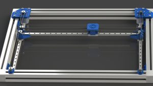
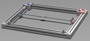
  • This week I worked on validating the sensor array setup. I built a small mockup in the lab as proof of concept. Here is the link to some pictures:
  • https://drive.google.com/drive/folders/14LiZyGlgnzooL9NhAiBFkcnJIqBjcocY?usp=sharing
  • I created a 4×3 sensor setup. Our initial idea was to have the sensors space ~4 cm apart. However, after this analysis, I realized that we could easily get a few more centimeters to reduce the total number of sensors in the setup. Instead of using a decoder to sweep through different sensors, I just brute force connected the sensors to the analog pins on the Arduino and viewed how they changed as I moved a test device across the setup. Here is the code I wrote:
  • https://drive.google.com/file/d/1c4kG5jKd9p7qzwbsMP-pJRLiSsfu-SFV/view?usp=drive_link
  • I experimented with different sensor distances, and for now have concluded that 5-6 cm between the sensors is good enough. This significantly reduces the number of sensors we will need to use.
  • I also validated that we would be able to use at least a primitive way of triangulation for device location based on the relative signal values of hall sensors nearest to the device.
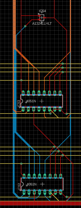
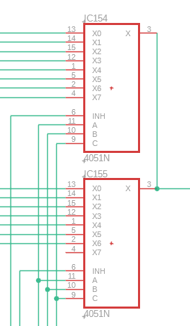
  • Me and Callum also deliberated the decoder setup further and have a much more concrete idea of what it is finally going to look like. Callum has also created a schematic of how everything is supposed to connect.


Is your progress on schedule or behind? If you are behind, what actions will be taken to catch up to the project schedule?

  • I think my progress as well as that of our team is on schedule!


What deliverables do you hope to complete in the next week?

  • Next week, if the charging coils come in, I want to finish testing and characterization. I want to see the actual effective range of different power values. I also want to see which layers and how many of them we can put in between the device and the coil before it stops charging at a fast enough rate. I also want to figure out a way to tap into the coil breakout PCB to utilize the charging current as a parameter for validation.
  • I also want to start assembly of the sensor array setup.
  • I also want to start working on the sensing code with Callum. We need to create a good interface between the decoders and the Arduino that will allow us to reliably sweep through different locations and make a location estimate based on signal values.

Luca’s Status Report for 2/24

What did you personally accomplish this week on the project? Give files or photos that demonstrate your progress. Prove to the reader that you put sufficient effort into the project over the course of the week (12+ hours).
I finished the CAD, and placed a lot of orders. The cad alone was likely at least 12 hours, with sourcing of a few other parts and finalizing of components were a few on top of that.

Is your progress on schedule or behind? If you are behind, what actions will be taken to catch up to the project schedule?
I believe we are on track for schedule. I certainly am.

What deliverables do you hope to complete in the next week?
Good progress assembling the stage, and begin printing parts. I will also need to measure every dimension of note on all the various parts that didn’t come from McMaster as Amazon is never accurate with their claims. This will most likely involve redesigning parts of the CAD. Hopefully I will have all the cad dimensionally finalized and have a decent amount of the parts printed with the rest under way.

Anirud’s Status Report for 02/17

What did you personally accomplish this week? Give files or photos that demonstrate your progress. Prove to the reader that you put sufficient effort into the project over the course of the week (12+ hours).

  • Ordered and tested Hall sensors. After a lot of research, I found these ultra-high sensitivity linear hall sensors:
  • https://content.instructables.com/ORIG/FHV/BQO4/JVR5YV9R/FHVBQO4JVR5YV9R.pdf
  • I also determined their range and region of optimal operation.
  • I did a comparative analysis between these sensors and the ones we had tested before (magnetometers, inductive coils). Concluded that these are best suited to our needs. The linear output of these sensors will also allow us to view the magnitude of change in the voltage across different sensors closest to the device and estimate the location of the device better than we would with a binary output.
  • This is the code I used on the Arduino to interface with the sensor: (OS → GitHub) https://drive.google.com/drive/folders/1XTErRDNUgChzzYopmD6_mG5LmT11oCgk?usp=sharing
  • I was using the Serial Monitor to view changes in Hall Voltage as the devices were brought closer. This was just for preliminary testing.
  • Spent 5–6 hours in the lab with Callum trying to figure out the ideal placement for the sensors to achieve the best coverage with minimum components. We came up with the result that our sensors can cover a 16 cm^2 area on the surface. So, our sensors will have to be ~4 cm apart. We will be making the sensing array on our own, using through-hole components and flat wiring. The acrylic surface will have indents created for the parts to sit in, this will allow for the highest proximity between the sensors and device.
  • After this, I also spent some time deliberating different sensing array setups to minimize cabling and maximize the ease of reading the output from various sensors. I decided on cascaded analog decoder chips that would allow us to use select lines to sweep different sensor locations and read sequentially, minimizing the number of Analog-In Arduino pins needed.
  • Callum has also created a CAD sensor schematic based on our discussion for us to use.


Is your progress on schedule or behind? If you are behind, what actions will be taken to catch up to the project schedule?

  • I think my progress as well as that of our team is on schedule!


What deliverables do you hope to complete in the next week?

  • Me and Callum are going to solder together a small-prototype sensing array to test with our phones and devices. Once we have made sure that they work and have adjusted the distancing and spacing, we will place the order for the components required for the sensing array. This should be done by next Thursday.
  • We have also purchased a couple of charging coils. They should be in by next week. We want to test their charging range and how they perform with different layers in between the charger and the device. This will allow us to decide on the surface material thickness and charging coil model.

Callum’s Status Report for 2/17

Personal Accomplishments:

This week, Anirud and I spoke about the requirements for a sensing matrix. I did some further work here after discussing project dimensions with Luca to find out how many sensors will create a good balance between reliability and workload.

After doing some research on viable ICs, I settled on using either 4051 (8to1) or 4067 (16to1) analog switches to multiplex the dozens of sensor signals into 16 or fewer analog signals (the limit for an Arduino Mega). Below are some sketches of how we expect the sensing matrix to be connected in the final project – however, using a custom PCB is certainly a stretch goal desired for the final project.


Project Schedule:

As with last week, we are keeping on track with our desired schedule and maintaining plenty of slack to utilize later in the project. However, as we end the design phase of our project, I expect progress to slow down due to component acquisition.

Next Week’s Goals:

Next week we need to do some final testing on the Hall-Effect sensors to better determine range and place orders for sensors and analog switch ICs (likely tomorrow). I hope to have a finalized design for the matrix and PCB design so we can start matrix assembly as soon as possible.


Team Status Report for 2/17

  1. What are the most significant risks that could jeopardize the success of the project? How are these risks being managed? What contingency plans are ready?
  • We are spending a lot of time designing, which is not necessarily a bad thing, but we might be underestimating the amount of time needed to do the assembly. We have slack time built into our schedule, but we don’t want to be in a situation where we get held up to for a large period of time. We are trying to expedite our design process without compromising on details and trying to get the parts ordered ASAP.
  • Another concern is that the 3D printed parts might not be strong enough to hold everything up. We are ordering enough filament so that we can re print parts if needed. We have also found metal replacements in case we need to order those (in the situation that plastic is not strong enough altogether)
  • We are working on the CAD models as much as possible with the listed dimensions for the parts. However, there may be errors in manufacturing that might prevent the components from integrating together properly. We are trying to account for this as much as possible by making parts that might be able to work even with minor errors in manufacturing. We are also trying to order parts that are as precise as possible. The extra filament also helps it we need to redesign and reprint parts.

2. Were any changes made to the existing design of the system (requirements, block diagram, system spec, etc.)? Why was this change necessary, what costs does the change incur, and how will these costs be mitigated going forward?

  • Initially, we had envisioned a PCB that would house the sensing array and be placed under the surface of our table. We were thinking of bolting it to the underside of the surface using some type of adhesive. This, however, would introduce two problems: 1. The hall sensors wouldn’t be as close as possible to the device 2. We would be introducing yet another relatively thick layer between the charging coil and the device, thereby reducing efficiency.
  • To mitigate some of these issues, I was looking into Ultra-thin flexible PCB’s and Copper Core PCB’s. The idea was to reduce thickness and possibly improve coil coupling by introducing a metal layer. These, however, were proving to be too expensive, especially with parts assembly. I took quotes from different websites and realized that the cost was too much for the benefit it could possibly provide.
  • So, we reevaluated our design and have come up with two possible alternatives:
    • Flexible plastic sheet to stick the through-hole components onto. We can then use flat wiring to connect these to the decoders and peripherals.
    • Laser etching indents into the underside of the tabletop surface to house the components and wiring. This second option is a little more tedious mechanically but could possibly improve the sensing efficiency due to more proximity between the sensors and devices and improve the elegance of the project.

3. Provide an updated schedule if changes have occurred.

  • No changes so far! Yay!

4. This is also the place to put some photos of your progress or to brag about component you got working.

Snippets of sensor matrix diagram

A was written by Callum, B was written by Luca and C was written by Anirud.

Part A: CALLUM … with respect to considerations of public health, safety or welfare. Note: The term ‘health’ refers to a state of well-being of people in both a physiological and psychological sense. ‘Safety’ is the absence of hazards and/or physical harm to persons. The term ‘welfare’ relates to the provision of the basic needs of people.

By using the Qi protocol to identify compatible Qi chargers above our charging coil, we will avoid inductively heating any metallic object that is placed on the table. This will reduce the likelihood of temperature hazards, whether they are burns or fire. We are currently discussing the use of a heat sink on our wireless charging module to further reduce heat hazards, but we need to test our charger to see if such a system is necessary.

Part B: LUCA … with consideration of social factors. Social factors relate to extended social groups having distinctive cultural, social, political, and/or economic organizations. They have importance to how people relate to each other and organize around social interests.

I’m not sure if this entirely applies to our project. It’s not something brought out into public, it’s not a necessity, and would not be impactful on how people would interact with others. It’s a pure convenience device, and would likely be priced as such if it were a real product. The only interaction others would have with this device would be in someone else’s residence. Even then, unless explicitly pointed out, guests would simply think it’s a normal table. Ideally, they wouldn’t even notice their phone was charged once they pick it up.

Part C: ANIRUD … with consideration of economic factors. Economic factors are those relating to the system of production, distribution, and consumption of goods and services.

When considering the economic factors of our wireless charging tabletop, several key aspects come into play:

  1. Production Efficiency: By integrating advanced technologies like hall sensors and an XY stage, our tabletop can potentially optimize production processes, leading to cost savings through increased efficiency and reduced waste. Additionally, leveraging modular design elements could facilitate easier assembly and scalability, further enhancing production efficiency.
  2. Cost-effectiveness: The implementation of wireless charging technology may initially incur higher manufacturing costs compared to traditional charging solutions. However, by optimizing production processes and leveraging economies of scale, we can work towards reducing the overall cost per unit, making the product more accessible to consumers while maintaining profitability.
  3. Distribution Channels: Partnering with established tech retailers, furniture manufacturers, or even hospitality businesses can provide access to diverse distribution channels, enabling us to reach a wider audience and increase market penetration. Additionally, exploring direct-to-consumer models through online platforms can offer greater flexibility in reaching target demographics.
  4. Consumer Adoption: Understanding consumer behavior and preferences is crucial for driving adoption of our wireless charging tabletop. Conducting market research to identify key consumer pain points, such as the need for convenient charging solutions in various environments, can inform product positioning and marketing strategies to effectively communicate the value proposition to potential buyers.
  5. Long-term Sustainability: Considering the environmental impact of our product throughout its lifecycle is essential for sustainable growth. Implementing eco-friendly materials, designing for recyclability, and minimizing energy consumption during use are all factors that can enhance the product’s appeal to environmentally conscious consumers and contribute to long-term economic sustainability.

Luca’s Status Report for 2/17

What did you personally accomplish this week on the project? Give files orphotos that demonstrate your progress. Prove to the reader that you put sufficienteffort into the project over the course of the week (12+ hours).

I became a slave to SolidWorks. I spent well over 30 hours this week doing cad and finalizing BOM. This folder contains periodic backups of my work.

Is your progress on schedule or behind? If you are behind, what actions will betaken to catch up to the project schedule?

I am scheduled to have the CAD finalized by end of next week (ideally before Thursday so we can order parts then). I believe I am well on my way to accomplishing this.

What deliverables do you hope to complete in the next week?

Finalized and reviewed CAD

Callum’s Status Report for 2/10

Progress this Week:

  • Discussed proposal feedback with Anirud and identified ways to better the testing and verification phase of the project.
  • Updated project schedule/Gantt chart to better reflect our plans after the proposal.
  • Tested inductance (proximity) sensors and found they would not be viable for the project. They had a short range and a binary output (neither of which will be feasible on a large scale).
  • Collaborated with Anirud and Luca in making various inductance coils to test device detection. Testing was conducted sending both 3V and 10V waves through the coils at 10KHz and reading the signal feedback with an oscilloscope.
  • Shortly tested magnetometers for use in sensing with Anirud by measuring effective range. More testing needs to be done on identifying device location.

Project Assessment:

The project is currently on track and we are ahead of schedule in testing. Anirud and I should have a good idea of how many sensors (likely magnetometers) that we will need for the project by the end of next week. This will give us more slack time that will be needed during the troubleshooting/integration process.

Next Week:

  • Finalize magnetometer testing (reevaluate if needed)
  • Draft a schematic for the device detection matrix
  • Begin testing a small matrix of sensors

Anirud’s Status Report for 2/10

Weekly Achievements:
1. Successfully presented the proposal abstract.
2. Advanced in identifying the optimal sensing mechanism for phone detection. Collaborated with Luca and Callum on experimenting with various inductance coils (differing in windings and diameters) to enhance phone sensing efficiency. Developed a basic Arduino interface for measuring inductance changes caused by proximity to a phone.
3. Conducted preliminary tests with Magnetometers, which showed promising range capabilities for phone detection over inductors. Created breakout boards for Arduino integration.

Progress Assessment:
– On track with the project timeline. We’re proactively focusing on implementation and testing with available resources, aiming for a clearer understanding of the final implementation in the upcoming weeks.

Goals for Next Week:
1. Initiate testing with Hall sensors, which appear more suitable for our requirements than magnetometers.
2. Develop a comprehensive test protocol for all considered sensing mechanisms to enhance the objectivity and effectiveness of our selection process.
3. Collaborate with the team to refine and expand our presentation slides for the next design review.

Team Status Report for 2/10

Current Risks to the Project:

Neither Magnetometers nor Hall-Effect Sensors will work:

In the event that we cannot viably sense devices with any of the tested methods, we plan to use IR LEDs and sensors to detect devices as they have a high probability of reliably detecting a new object. We want to avoid this approach as using IR means that we will detect all objects on the table and will require an IR-transparent material to be used as the table top.

Design Changes:

We will no longer be using induction to detect devices due to range limitations. For the approach to work, we would need to tile the entire underside of the table with coils. This would greatly reduce efficiency and increase project costs.

Updated Gantt Chart:

Luca’s Status Report for 2/10

  • What did you personally accomplish this week on the project? Give files or photos that demonstrate your progress. Prove to the reader that you put sufficient effort into the project over the course of the week (12+ hours).
    • I found an open source project for a marble-in-the-sand drawing table, and went through all constituent parts and found links for them all. This was done and added to a spreadsheet found here.
    • I set up the website with everything specified in the website guidance file on canvas. I also completely redesigned the website, created a logo, and created a good tile-able background (harder than it sounds). While the final version of each is present on the site, the Photoshop file and previous outputs are stored in our drive.
    • I worked with Callum and Anirud in lab to determine the feasibility of induction sensing. We concluded it likely it’s reasonable, and we will now continue testing magnetometers and hall effect sensors.
  • Is your progress on schedule or behind? If you are behind, what actions will betaken to catch up to the project schedule?
    • I believe we are on schedule. Next week I plan to throw together a finalized CAD of the entire assembly, and time permitting, begin ordering constituent parts.
  • What deliverables do you hope to complete in the next week
    • A mostly finished, Finalized CAD assembly of our project. Because discussion and trial and error takes time, I’m optimistic to have entirely finished by the end of next week.