Now that you have some portions of your project built, and entering into the verification and validation phase of your project, provide a comprehensive update on what tests you have run or are planning to run. In particular, how will you analyze the anticipated measured results to verify your contribution to the project meets the engineering design requirements or the use case requirements?
Verification is usually related to your own subsystem and is likely to be discussed in your individual reports.
Validation is usually related to your overall project and is likely to be discussed in your team reports.
Use Case Requirements, Testing Plans:
Fast response time of under 3 seconds (Tentative)
- We will measure the time it takes from signal dispatch to the actual stopping by logging in to the Arduino terminal.
- We know we will have satisfied the use case requirements if our response time is less than 3 seconds
- We anticipate that because of the responsiveness of the Arduino and the speed it can transmit signals achieving a response time below 3 seconds should be very feasible
Levitation System
- We will manually verify our carrier’s height above the track with physical measurements.
- We will have met our design and use case requirements if we can achieve a levitation of 0.8 inches.
- The levitation distance will be measured from the track’s top to the carrier’s bottom.
- We currently have achieved a levitation of 1 inch, meeting our requirement
Object Obstruction Module
- We will manually set up instructions on the track and measure the distance at which the carrier stops before the obstacle.
- We ideally want the carrier to stop at least one carrier length before the obstacle at a minimum of 2 centimeters (design requirement) before the obstacle given the limitations of our ultrasonic sensors.
- Overall we want our carrier to be 75% accurate when detecting obstacles.
Speed (Tentative)
- We will use a speed detector as well as look at the peak points of the linear hall affect sensor to detect how fast the carrier travels from one coil to the next
- We previously stated that we would want our carrier to travel around 2 mph
Risks:
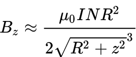
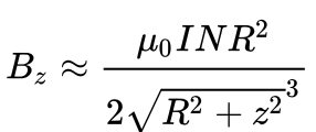
Strength of Magnetic Field From Coil
Our track relies on solenoid coils to help propel the carrier across the track. With the limited budget for the project, we are hoping to maximize the magnetic field so then it would be strong enough to propel the carrier a large enough distance, to decrease the amount of coils needed on the track. Since it is unknown of the effects of the currently designed coils with the track and carrier, we run the risk of having a coil not being strong enough, thus the need to redesign the coils which will only take up more time and more resources.
Friction from Design
Our current 3D-printed track has a guiding rail. This was created to support the carrier but it is limiting the carrier’s mobility. Currently, several gaps between the carrier and track are too small. This has created little room for the carrier to levitate, limiting the levitation magnets. Additionally, the friction between the track and carrier would make it harder for the speed-up coils to propel the track.
Wireless communication
Our project is dependent on the carrier circuit communicating with the track circuit. The stop, start, and speed system requires that the linear hall effect can communicate with the H-bridges to adjust the speed of the carrier through the speed-up coils. The obstruction system requires that the ultrasonic sensor can communicate with the H-Bridge to stop the carrier if there is something within 10 cm of the carrier. We are attempting to do this through the HC-05, a Bluetooth communication — that can allow Arduino to communicate. We are still working on writing the code that would allow this communication to take place. Not being able to complete this code would mean there is no way for either sensor to communicate with the track.
Design Changes:
None to be reported
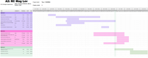
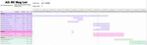
Schedule:
No update to schedule. We are on track.