- Ethics Meeting (2hr)
- Discusses Ethics of our project with class
- Independent Work (10hr)
- Construct cardboard model of two-to-one carrier/track magnets design
- CAD design for one-to-one carrier/track circle magnets design
- CAD design for two-to-one carrier/track circle magnets design
- CAD design for two-to-one carrier/track rectangle magnets design
- Determined a way to distinguish stops with a magnetometer
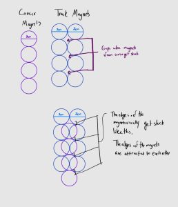
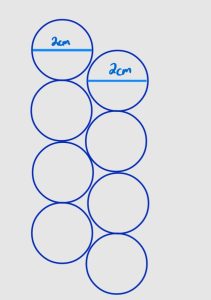
Through out this week, I worked on solidifying the dimensions for the one-to-one track/carrier magnet design and the two-to-one track/carrier magnet design. The main changes to models involved spacing out the magnets on the carrier for the two to one magnet. This mainly do to not having enough magnets when I constructed the cardboard prototype but this design was significantly more stable than the one-to-one design but also levitated higher. However, there were still some issues with the magnets getting stuck in between gaps in the track. This was a large reason why we decided to order rectangular magnets
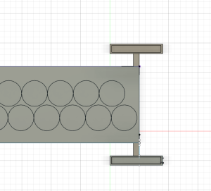
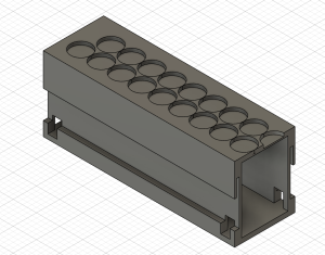
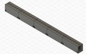
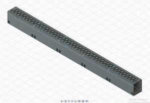
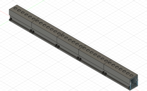
I also constructed CAD models for the different designs. For track designs, I created the one-to-one track circle magnet design, the two-to-one track/carrier circle magnet design, and the track design for the two-to-one track/carrier rectangle magnets system(pictures below). The circle magnet designs are based of the finalized dimensions from the cardboard prototypes. Since the rectangle magnets have not come in yet, this design was based off of predicted behavior based on what we have seen with the circle magnets and the dimensions of the rectangle magnets. One major consideration for the rectangular design is how to orient the magnets. Currently, the longer side of the rectangle is along the track and there is large gap between the lines of magnets. While the magnets are less likely to get stuck since it is a straightaway, sudden movement in the carrier could result in sides of the magnets getting stuck like in past designs. I would like to create a cardboard prototype of this structure then edit the current CAD design based on the results.
One-to-one track/carrier circle magnets
Two-to-one track/carrier circle magnets
Two-to-one track/carrier rectangle magnet (2mm between lines)

Two-to-one track/carrier rectangle magnet (10mm between lines)
Carrier
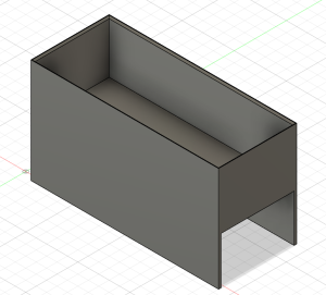
Bottom of Carrier
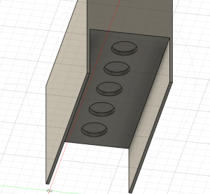
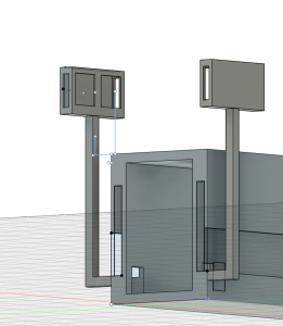
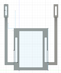
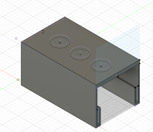
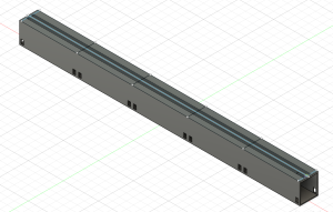
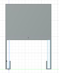
I also created a derivative of the one-to-one design with a guiding rail for the carrier. This would be in place to help with the stability. This was difficult to construct with cardboard so I would like to print this soon to see if the dimensions of the rail properly account for the height of levitation and sudden movements with the carrier.
One-to-one guided design
Side of one-to-one guided design
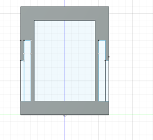
Carrier guided design
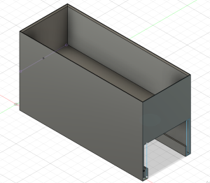
Side of carrier guided design
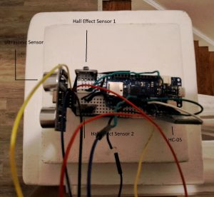
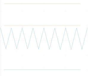
I also worked with magnetometers to attempt to make a stop start system. This was done though attaching two magnetometers to face opposite sides of a breadboard to simulate the sides of the carrier. I tested how the plot changed as I moved magnets along both sides and switched their polarity while adjusting the sensitivity of the magnetometers. Following a few tests, I noticed that the amplitude of the signal on the plot changed based on the polarity of the magnets, the amount of magnets, and the magnetometer the magnets was in front of. Based of this, I think a baseline signal can be created and significant changes in either side of the signal can represent a stop.
No Magnet near either magnetometer
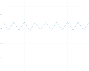
Negative polarity near magnetometer 1
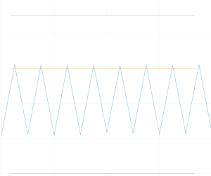
Negativity polarity near magnetometer 2
Next Week
Next week, I would like to work on making more carrier designs. Also, I would like to print some portion of all the above designs to see if there are any major design issues I missed. I would also like to continue working with the magnetometer and start working with the ultrasonic sensors to make a full start, stop system.