I spent the first half of this week working on getting our interim demo ready for wednesday. The first thing that Neha and I focused on was integrating the LED and LCD displays with the output of the pathfinding code. Originally, we were able to display directions, but after reformatting our code to import the functions that we used, we were able to create a file to run our loop function that could utilize these functions. After integrating, we could specify a path, and the node would show the direction to go (Left, right, up, down) on the LEDs, as well as the path to follow on the LCD display.
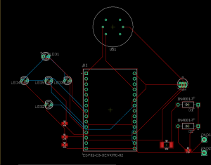
The other main thing that I worked on this week was the pcb design. A big part of this was adding the backup battery circuit to our schematic, which is something that Neha and I worked on. After this, I also cleaned up the LED circuitry because I found that I could reduce the number of resistors needed by running the LEDs through one resistor to ground instead of each LED having its own resistor. However, Neha and I did find out that we would not be able to do this for the red and green LEDs together. We attempted to do this on our breadboard and got errors when uploading to our ESP32. I am assuming this is because of the different forward voltages of the LEDs. After making these changes I created a board layout by moving all of the components onto a board in Eagle and using the autorouter. The autorouter returned a board layout that used two layers. I was initially hoping that we would be able to do it on one layer, so I spent some time looking into this and seeing if there are any changes I can make to only use 1 layer.

One of the tests that I am planning on running is testing how long our system can run on the battery supply. For this I want to create a circuit so that I can test all of the components at the same time. Once I can do this, I will see if our system can run for 24 hours straight. 24 hours was our design requirement. To begin this task I will collect all of the software that I need to run the individual pieces. I am hoping to accomplish this this coming week. Another test that I want to conduct is the testing of the system as a whole. Once Neha, Jason, and I’s code is integrated, I think we should begin testing by holding a flame to the nodes and looking for the correct output on our LED and LCD displays. Also, as I mentioned previously, I feel that we need to test our system by wiring it up the same way that our PCB design specifies. After this we will test to make sure that all of the components are working correctly to ensure that our PCB design is valid on wall power and battery power.
This week, one of the tasks that I want to complete is verifying our PCB layout. With the exception of the battery charging circuit, we have tested the individual components separately, but together. This is something that I for sure want to accomplish before we begin manufacturing the final PCBs. This way we can also fine tune resistance values and hole sizes to prevent issues we may have further down the road with our design. Another thing that I wish to accomplish is to integrate the display code with Jasons pathfinding code. Currently we are able to take a path, so I do not think that there will be too much work to integrate these systems. One other taks I want to finish this week is to find a floor plan on campus that we will use to create our video demo. As some of our code will be hardcoded to match the building specifically, having the building in mind may save us some time.
Currently I believe that I am on schedule. There were some changes that we made to our schedule this week, but I believe we covered these changes in our interim demo. Some of these included changes for the PCB because we were thinking that we may make them ourselves. However, I am still on track to finish my tasks on time, according to our new schedule.
