Team Status Report 4/29

List all unit tests and overall system test carried out for experimentation of the system. List any findings and design changes made from your analysis of test results and other data obtained from the experimentation.

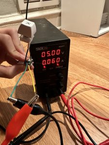
The unit tests done were the testing of Battery Life, Stability, Size, Reliability, Hot-Swappability, and Wireless Connectivity. Battery life was tested by measuring the current draw over a period of time, and determining the average active and passive power draw. Stability was measured by taking a video of the key being pressed while secured to the plate, and measuring the side to side wobble recorded from the video. The size was measured with calipers. The reliability was measured by pressing each key 10 times and ensuring that all 10 keypresses were received. We found that pressing the keys very quickly in this test would cause issues with key presses not registering, so changes to the receiver code were made such that these rapid keypresses would still be registered.

Overall system tests carried out were Layout Freedom, Weight, and Latency. We tested the layout freedom by moving the 16 keys around in various positions and ensuring that all of them were still able to transmit a keypress back to the receiver. We tested the weight by putting all 16 keys and baseplate onto a scale, and recording the resulting weight. No changes were made as a result of any of these tests.

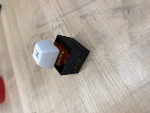
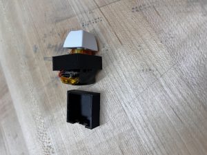
Testing images found in final presentation.

Currently, the most significant risk is that we will not have time to finish the various assignments on time, as we all have finals and other assignments due the same week. However, if we manage our time well, we should be able to finish everything on time.

No updates to the schedule or design requirements have been made.

Team Status Report 4/22

This week we believe the most significant risk is that we will not be able to get enough 3D printed housings to enclose every switch. So far, we have not been able to get the settings down so that the switches housings will not fall apart during or after the print. Additionally, even if we were able to get the prints to work, we would need to print 16 housings without issue. If we end up not having enough time to print all the housings, then the rest of the housings can be made out of paper or cardboard as a last ditch replacement.

We had to change the 3D housing design slightly, making the housing skinnier and with less wall thickness. However, this ended up causing the 3D prints to fail more often, so we had to redesign the housing a third time with the original 2mm wall thickness. These did not incur any additional costs besides the increased 3D printing costs from the prototyping. In fact, since the overall housing is smaller, it would actually be slightly cheaper due to the reduced

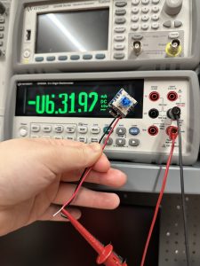
The schedule remains the same. Attached below is a picture of the reading of the current the switch draws once the switch is on. This week, we also performed almost all of the testing required to verify that our use case requirements were met. The only test that we did not perform was the test of whether or not the switch would be stable on the base, as we did not have the 3D printed housings or the 3M Dual-Lock on hand. However, this test will be performed next week as soon as we have both of the items.

Team Status Report 4/8

The most significant risk to our project currently is the finishing and functionality of the wireless transmitter boards due to their strange behavior, which we have explained extensively in person as well as in our individual status reports. We are managing this risk by trying multiple solutions, including buying smaller coil transmitter boards that come from a different set of testing boards than the set we bought along with reaching out for help to the teaching staff. Our contingency plan in case the wireless charging completely does not work is to have strips of metal as the charger and put contact pads on the bottom of our keys instead.

Another risk is connecting more than 7 keys to connect to one BLE receiver. The new boards that we bought since we thought could raise the limit on the number of BLE connections (which is limited by the allotted memory to each BLE thread), but even after going through the process of raising the limit in the system constants, only 2 BLE connections would ever actually go through. This led us to try working on increasing the limit on our original main microcontroller, but the processes found online are from 5-6 years ago and no longer work. More information can be found in Ben’s status report.  The backup plan in case we cannot increase this limit is to use multiple BLE receivers (3 max).

No changes were made to the existing design of the system.

The schedule is the same except the wireless charging task has been extended and we are working on that and other tasks concurrently.

Here are some pictures of our updated app and app output files:

Here is our newest iterations of the 3D printed housing:

Team Status Report

What are the most significant risks that could jeopardize the success of theproject? How are these risks being managed? What contingency plans are ready?

Currently some of the risks are that we will be unable to connect all 16 intended keys in an efficient and timely manner. This is because if we are unable to increase the limit on the number of keys that can be connected to a single receiver device, it would mean we would have to network multiple receiver devices together to receive all the signals from the individual keys. While this may work for our proof of concept, it would be impractical for an actual, scaled-up keyboard. To manage this risk, we are considering using one of the Seeed BLE boards as the receiver instead, since the nrf52840 can support up to 20 simultaneous BLE connections.

An additional risk is the wireless charging. While the receiver coil is working, the transmitter coil has been giving us issues all week with it either shorting or not outputting a nice sinusoidal signal. To address this, we plan to buy a new transmitter module with a coil that more closely matches the dimensions of the receiver coil and see if that is able to work. If not, then we plan on redesigning the housing slightly to accommodate the slightly longer receiver that comes with the smaller coil.

A change in the receiver microcontroller may be necessary as the Arduino Nano 33 IOT does not seem to be able to support the number of switches we want connected. Additionally, the width of the housing may need to be increased to accommodate the PCB for the wireless charger. Since we already have the BLE boards, no additional cost is borne there. However, we will need to spend an additional 11 dollars on the wireless charger. The schedule remains the same at this time.

https://ibb.co/S6DHYrk <- Pictures of Coil readings

Team Status Report 3/25

Currently the largest risk is still the wireless charging not working correctly. We received the wireless charging kit this week, but since everyone was busy with their own weekly tasks, the wireless charging was not tested beyond basic verification that it worked.  Additionally, we are worried about the functionality of the wireless charging through the 3D printed housing. We can mitigate the risk of the wireless charging not delivering enough power somewhat by lowering the idle power consumption of the key device, thus allowing the battery to trickle charge with an extremely low current input. As for the housing, it would be possible to make the bottom wall of the housing extra thin to allow for minimal interference with the wireless charging coils. Another risk is that the configurator software may not be able to precisely identify which of the keys is being programmed at any given time. We plan to mitigate this using numbered keycaps on top of each key, such that it would be possible to select a key to be programmed. Alternatively, we could have a system where the user needs to press a key, which would highlight it on the interface and allow the user to set a command.

The spec has not changed in the last week, and no additional costs have been incurred.

Attached below are photos of the key programming interface prototype and the key housing prototype.

Team Status Report 3/18

Currently the risks are the same from last week, but much more mitigated now. We have a 3D design of the housing and can confirm the dimensions in the following week when we have fully assembled keys to see how much room we can have and shave down. Currently the dimensions are 25x25x23 mm^3 (w x l x h), and this is with most likely more leeway than is needed. Since it appears we can have 3D housing finished soon, that worry is one less. The programming software unfortunately cannot be started until we have working prototype of the whole system set up, however with the progress of the receiver and BLE boards, we should be reaching that goal soon.

The wireless charging kits came this week so that we may begin working on the proof of concept next week as well. This will be helpful in determining on how fast the charging will be once we have made our adjustments.

No significant changes have been made since last update.

Our schedule is on track as we were able to do 3D housing this week.

New tools: Using Solid Works instead of Autodesk due to more familiarity and no need to import the BLE footprint. Solder iron to solder the keys together with the hot swap boards.

Currently with 4 keys connecting to one another, the receiver acting as a keyboard, 2 key modules assembled, and solid works file of the 3D housing(forgot to take screenshot), we have made good progress.

Team Status Report 3/11

Currently, we believe the most significant risks are that the wireless charging may not be able to deliver enough current to charge the battery sufficiently quickly and that the timeline may not allow for sufficient time to iterate both the programming software and the design of the 3D printed housing by the time the project is due. In terms of wireless charging, we are managing the risk by focusing development on getting a single switch to wireless charge correctly as a proof of concept, and having the remaining switches charge from USB as a backup. In terms of the software, we plan to focus on functionality first and then add any aesthetic improvements only if we have time. The same goes for the 3D printed housing. We may have to end up sacrificing some of the dimension design requirements to get the housing working at first, but then we plan to see what we can shave down after the fact.

We added a single switch PCB as an interface between the Cherry MX switch and the Seeed board. This was necessary as we found that our original plan of soldering wires between the switches and Seeed board would not meet the requirement of having hotswap capabilities. Additionally, it would make assembly nearly impossible as the switch would have to somehow be soldered inside the housing. This incurs an additional $1.50 cost per switch, but since the PCBs are so simple, it would cost a lot less if we ordered custom PCBs (~$5 on JLPCB). However, since we want to begin putting everything together more quickly, Amazon seemed to be the better choice. With this change, we may need to increase the dimensions of the housing to occupy a footprint of 25mmx22mm as current measurements of the battery + seeed setup already are pushing 22mm in the length dimension. We believe that this will not present that large of a usability issue however, since that is about the difference in spacing between a laptop keyboard and a Cherry MX style keyboard, and thus we do not expect users to be able to notice a difference.

There are no updates to the schedule currently. We have attached images of our charging testing and a video of the two switch connection working.

New tools:

To design the software, we would need to learn some sort of GUI creation library like PyGUI or GTK. To design the 3D printed housing, we plan on learning how to design using Autodesk, since it allows us to import Eagle footprints in order to give us an idea of the dimensions of the Seeed board and other components.

Video link: https://youtu.be/-SggOrEHb1I

Team Status Report 2/11

We believe the most significant risks to the success of the project currently are the feasibility of wireless charging, the maximum number of devices possible through BLE, and the integration of all the components into the 22mm height permitted. For wireless charging, our backup plan is that the microcontrollers can pass through charge to the LIPO batteries via USB. For the BLE issue, we are managing the risk by looking into alternative BLE standards such as bluetooth mesh, with the backup plan to make some of the keys act as receivers pair multiple of the receivers with the central microcontroller. For the integration, we can use low profile cherry switches and cut down on some of the “nice to haves” such as hot swap capabilities to reduce the Z-height.

There have been no changes so far to the design of the system so far as we have not gotten enough parts in to experience any real integration challenges yet.

We have some pictures of a small inductive charger working posted in Zhejia’s status report.