Team Status Report 4/8

The most significant risk to our project currently is the finishing and functionality of the wireless transmitter boards due to their strange behavior, which we have explained extensively in person as well as in our individual status reports. We are managing this risk by trying multiple solutions, including buying smaller coil transmitter boards that come from a different set of testing boards than the set we bought along with reaching out for help to the teaching staff. Our contingency plan in case the wireless charging completely does not work is to have strips of metal as the charger and put contact pads on the bottom of our keys instead.

Another risk is connecting more than 7 keys to connect to one BLE receiver. The new boards that we bought since we thought could raise the limit on the number of BLE connections (which is limited by the allotted memory to each BLE thread), but even after going through the process of raising the limit in the system constants, only 2 BLE connections would ever actually go through. This led us to try working on increasing the limit on our original main microcontroller, but the processes found online are from 5-6 years ago and no longer work. More information can be found in Ben’s status report.  The backup plan in case we cannot increase this limit is to use multiple BLE receivers (3 max).

No changes were made to the existing design of the system.

The schedule is the same except the wireless charging task has been extended and we are working on that and other tasks concurrently.

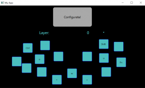
Here are some pictures of our updated app and app output files:

Here is our newest iterations of the 3D printed housing:

Zhejia’s Status Report 4/8

This week, I first worked with Korene to try to decipher what exactly the equivalent circuits for the 2 chips on the wireless transmitter are and we tried to solder wires from the resistors and capacitors on the board so we could connect it to a breadboard and easily swap them out, but one of the resistor positionings was quite awkward, so on both attempts, we ended up ripping the pad off of the board, rending the boards unusable. (We made 1 more attempt after the first on failed). We also did some testing on the connection between the 2 chips and discovered that the first chip, the oscillator, was not the one causing the shorting issue since it still operated fine (outputted a consistent square wave) even when we switched out the inductors or completely removed them, which means the issue is likely with the T5336, which is the one completely lacking documentation but it is likely a power MOSFET, so maybe the issues have to do with it’s operating point?

After some setbacks there, I worked more on the keyboard configuration software and implemented freely moving keys, so now the keys can be moved by the user to any location within a rectangular “baseplate” and still function properly.

Additionally, I also implemented the save functionality and it now saves the key binds and the positions of the keys to a file so they can be kept for next time. The idea is also to interface this with bens code and only upload a text file to the USB device rather than reflashing the entire board to change just the key binds.

Lastly, I started adding the components to make the user be able to configure different key binds on to different layers. (Typically, personal keyboards allows you to set a key to toggle layers, which changes all the key binds on the keyboard depending on the current layer).

I will be testing the visible wobble of the keys. I will be doing this by recording the typing with a video camera and seeing how much the keys deviate from a central baseline. Additionally, I will be measuring the charging time and rate. Charging time will be measured using a timer and a battery level readout from the keys. Charging rate will be measured using a ammeter connected to the battery charging circuitry. I will also be measuring the costs associated with each key. This will be done by looking at the spreadsheet and figuring out an amortized cost per key for the keyboard.

I am slightly behind schedule for the wireless charging due to the issues with identifying the chips and how they function with the lack of documentation. I am on schedule with the UI create. We plan to discuss with Prof. Tamal tomorrow (Sunday) about issue with the chips.

Next week, I plan to implement most of the functionality of the UI and start interfacing with the microcontroller if there is time. I also plan on making progress and figuring out the situation with the wireless chips, but that progress depends on our discussion with Prof. Tamal.

Zhejia’s Status Report 3/25

This week, I first worked on modifying the evaluation boards that arrived from amazon with Korene, desoldering the inductors from a pair of them and measuring the inductance by scraping off the inductive coating and using an LCR meter. Additionally, we also characterized the oscillation frequency the transmitter board was at (around 64kHz). We also tried to follow the traces and figure out which capacitors and resistors were contributing to what, which we mostly figured out, and then we tried to measure the relevant onboard capacitors with the LCR meter to find the ideal resonance frequency, but the calculations ended up way off from the actual operating frequency of 64kHz, so more investigation next week is necessary.

Next, I worked on updating the keyboard driver code on the main microcontroller to accommodate features including:

  • modifier keys (keys that are not visible letters like Ctrl and Shift)
  • multiple key presses at the same time
  • long key presses typing multiple letters (like aaaaaaaa for holding down ‘a’)
  • preliminary different layer support (different ‘layers’ have different keybinds)

Lastly, I started work on a basic GUI for the keyboard configuration software using pyqt6. I ran into some problems with my python installation location and had to spend some time finding where different versions of python were installed in my windows system and editing my path until the installed pyqt6 could be used (I was missing a python3.dll file). After that I created this preliminary GUI:

It functions as you would expect: Configurate configures the keyboard shortcuts typed into the keys (by generating an arduino code file), and to differentiate between the keys, when you click a physical key, the corresponding digital key changes color/lights up. Additionally, I plan to have the keys be draggable to different locations in the UI for users to mimic their current layout if they would like.
However, most of these functionalities are not yet implemented.

I am on schedule.

Next week, I hope to work with Korene to get a pair of evaluation boards to work with our small inductors. This will likely take a long time. If I have more time, I will finish implementing essential features for the configuration GUI.

Zhejia’s Status Report 3/11

This week, I worked on the interface between the magnetic charging and the seeed xiao BLE board. I researched the schematic diagrams and tested which pins can be used to charge the LIPO battery through the seeed board. We don’t want to directly charge the LIPO since the seeed board has a battery management system (BMS) already (BQ25100) which guarantees safe charging since overcharging LIPO batteries is dangerous. Looking through this schematic diagram, which is for the sense version of the board, but is the same ignoring the sense components, I found that charging is done though V_BUS, which is connected to the BMS, so the next step was trying to find an external pin that connected to V_BUS.  The pinout sheet given on the official website had it labeled as AD2 instead, so I spent some time trying to find which external pin was AD2 to no avail. Later, after examining the schematic again, I realized that this pinout sheet was for the nrf52840 chip instead of the seeed board. Although none of the pinout diagrams for the board officially labelled a pin as V_BUS, I presumed V_USB was likely connected to V_BUS since the USB was connected to V_BUS in the schematic. Then I used my power supply to provide 5V to the V_USB pin (pictures on the team status report), and at first it did not work, so I thought that V_USB might be connected to V_IN instead of V_USB, which would be an issue, but actually, the issue was connecting the ground pin to the ground terminal of the power supply did not work and it instead needed to be connected to the negative terminal of the power supply. In the end, I successfully charged the LIPO with 3.25V-5.5V although the 3.25V only provided 8mA of current while it basically gets full current of 60mA at 4.35V which matches the recommended operating conditions of V_USB in the datasheet. According to the datasheet, we also should be able to charge with low voltages using the VDD pin, but I have not tested that.

Of course, I worked on the design report as well.

My progress is on schedule, and I plan to research and start writing the keyboard driver software to send keypress data to the computer next week.

Team Status Report – 2/25

Risks:

The turnaround time for PCBs added with the shipping time of the XKT ICs and testing the PCB is cutting off much of our margin for error allowance and is dangerously late. 3 weeks for PCB turnaround, 1 week for IC chip shipping, and 1 week for PCB testing goes for a total of 5 weeks, which would not leave us enough time to remake the PCB if anything goes wrong.

To manage this, we will make the PCB layout next week without specific values for the capacitors to have the PCB design basically ready except for specific values. Additionally, we will test the circuit on a breadboard before sending the PCBs out to fabricate, and ideally, we can choose a fabrication lab that will have a faster than 3-week turnaround.

Another risk is the latency of the BLE communication, since BLE only allows one server to be connect to one client at a time, and there is a minimum connection time of ~7ms required. Our current mitigation strategy is to daisy-chain multiple keys together so each seeed BLE board can connect as a client to one other board and also connect as a server to a different board. Aka the boards can for a chain of board1 -> board2 -> board3 -> board4 -> … -> Main board and board9-> board10 -> etc to minimize the connection switching necessary.  The number of chains that would give the fastest connection is still to be determined next week.

Changes:

No changes were made to the design of the system since last week.

Schedule updates:

Since the IC and PCB will take at least a week to ship and our design was delayed due to having issues figuring out the wireless charging system, we have shifted later tasks such as writing/designing the configurator software up.

Team Work Adjustments:

The new design challenge of delivering enough current through the wireless inductive charging transmitter resulted in a week of much research and comparing pros and cons to creating the circuit ourselves and what types of chips we could feasibly get and use, and has pushed around our schedule such that we will have to push back integration of our entire wireless charging system to when the IC chips and coils arrive. Additionally, the PCB send out for fabrication was also delayed by this week and the IC chip shipping week, so in order to maximally use the weeks of waiting, we have adjusted our work assignments to preparing for when components arrive and focusing on other parts of our project that don’t require those components.

Zhejia’s Status Report – 2/25

This week, Korene and I worked on finding ways to improve the power delivery of the magnetic charging system since from last week, we discovered that a simple circuit would not deliver enough current to charge the seeed xiao board. We first spent some time trying to look for power amplifiers that would work at the high AC frequencies that we would be amplifying as well as a voltage-controlled sine wave oscillators, which were a bit elusive, and a lot of circuit diagrams came up instead. Many of the ICs that came up turned out to generate non-sine waves (many trapezoidal looking waves – basically square waves with rise and fall times) and figuring out which waveform the VCO outputted was often not on the datasheet. After talking a bit with Professor Tamal about using an ecosystem, we switched direction to looking into Qi wireless charging compliant ICs and boards, where we found a couple small sized wireless charging kits (Wireless Charging 10mm Coil 150mA Wireless Transmitter + Receiver Power Charger 5V Output (10mm Coil 150mA) (amazon.com)) on amazon and zoomed in on the product pictures to get the board name/chip name – XKT-412. This chip’s datasheet was only in Chinese and could only be found on AliExpress and Amazon. After some attempts at deciphering it, we moved on to trying to find Wireless Charging ICs on digikey. From there, we found some good ICs on digikey that came with an example project but those chips were obsolete and could no longer be bought. Then, we went over our seeed board’s battery management system requirements and ordered wireless charging transmitters by current, and many of them had quite low (3-3.6V) voltages, which we thought was too low at the time, and the ones with higher voltages either had tiny currents, no listed current, or were obsolete and were not sold anymore. We then looked on mouser and looked through many viable options, and unfortunately, many of them were not stocked (BD570xx Qi / PMA Wireless Power ICs – ROHM | Mouser). We eventually found a chip that had 4.5-24V along with 87mA current that was stocked, but that chip had 68 pins and was very complex and the datasheet did not give us a lot of information on how to use it or how the many pins worked. This was when we reached out on slack for help and moved to looking at the application notes instead. We then had a meeting with our instructors about this, and tried to look for more simple ICs since that IC had many components we do not need, and in the end we circled back to the amazon wireless charging kits, and found another variant of the XKT series, the XKT-510, which actually had a datasheet in English, although not with perfect translations (XKT-510.pdf (sakura.ne.jp)) along with example wiring circuits of both the transmitter and receiver to go along with it, and we decided that ideally, we would go with these chips as their pinouts and circuits were much more manageable than the 40-68 pin wireless charging ICs we found on digikey and mouser.

Our progress is slightly behind as although I hoped to resolve the power and current issues by this week, the extensive amount of research we had to do as well as the shipping time for the XKT ICs will push the power integration and PCB manufacturing on Korene’s part further back than we anticipated. With this adjustment in schedule, in the meantime, I can find the resonance for the official coils we ordered as well as start working on my other task, the design of the keyboard configuration software instead and shift around my schedule a bit.

Next week, I hope to record the required capacitor values for resonance for the industrially made coils we ordered, which should arrive soon (?) and work on the design and plan for the software configurations that will go on the main microcontroller, which for now is just another seeed xiao board. We should also order samples to test the XKT chips as soon as possible due to their weeklong shipping times.

Zhejia’s Status Report – 2/18

This week Korene and I troubleshooted our resonance issues from last week and found that the signal generators in the 220 Lab increased in voltage as the frequency increased, leading to being unable to spot the peak amplitude on the oscilloscope (the math->division menu item was also quite noisy). However, we moved to using the ADALM’s spectrum analyzer and found the resonance with no problem after setting that up.

After that, we also constructed the rectifier/receiver and transmitter circuits on breadboards and got it to output ~6V, which is the lowest charging voltage the Seeed Xiao microcontroller’s battery management system can take, but at too low of a current.

These are skills we learned in 18-220 and 18-100.

Here are some pictures and diagrams of our constructed circuits:

I also worked on the design PowerPoint slides with everyone else.

My progress is on schedule, and next week, I plan to try to increase the current delivered and try attaching the battery to microcontroller to a breadboarded circuit and get the microcontroller charging.

Zhejia’s Status Report for 2/4

This week, I worked on the website, specifically the introduction and wrangled with the formatting, and I worked on the proposal slides as well. We also spent significant amounts of time brainstorming over the recommendations and comments on our project idea and researching the feasibility of our project and solutions. For example, Korene and I did extensive research on the pros and cons of moving to a new project versus the validity of our use case, and solidified our justifications/explanations for our metrics, which we may not have explained well in the abstract. Additionally, we also researched various microcontrollers and compiled reasoning behind buying vs making our PCBs.

While a concrete weekly schedule has not been drafted for this week, we are on schedule with the pace of the course and ready for next week.

Next week, I hope to successfully implement resonance charging on a small scale to confirm the process and feasibility of wireless charging each key. We will need to work in the 220 lab and research the mechanism behind resonance charging, which is opposite to inductive charging.