
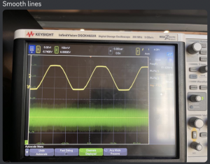
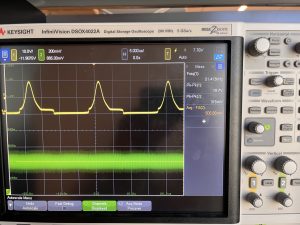
Over the past week, Zhejia and I have developed the plan for the inductive charging and created the proof of concept circuitry for it. Currently, we are now searching for the specific parts for the rest, but have found the inductive coils to buy (buying because it is more reliable to have the same inductance rating and be more consistent). Photos of the circuitry are on Zhejia’s Status Report. Some unknown results are why the current input and output appear to be so low and when measuring output current the voltage readings on the oscillator become warped. (top picture below is as normal measurement, bottom photo is when we measure for output current)
Next we need to make our calculations based around the 8.32uH inductors and then we can make a base schematic for the PCB. We plan to buy materials at beginning of the week to get them at the end of the week. Then test on the breadboard and complete the schematic and layout of the PCB to be sent out for fabrication(week after getting parts to buy)
We should be on schedule, but in practice a bit late in terms of when to send out a PCB board to fabricate. I hope there is still enough time to order one and then order another just in case.
A lot of 220 is being used here as it provided the best overview of a diverse number of components. We used Lab2a handout to build the full bridge rectifier and voltage regulator and lab4a to build the circuit to measure for resonance frequency. It’s a lot easier the second/third time around and cool to see it used to actually charge inductively! Some 18310 and 18320 knowledge is being used because of knowing about mosfets (and soon 18421 when we start looking at what power amplifiers to use in order to boost our power)