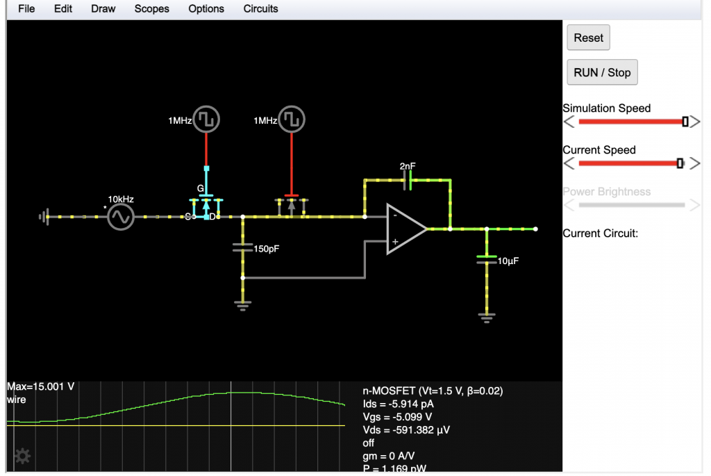
Recently I’ve been focusing on two main tasks: programmable analog filter design and FPGA I/O allocation. The hybrid synth requires six analog filter paths with programmable highpass and lowpass cutoff frequencies that are controlled by the FPGA. We chose a switched capacitor architecture in which two MOSFETs are driven with non-overlapping clocks. to emulate a programmable resistor. The topology was selected, components were sized, and a simulation was run to verify the results across the audio frequency range. We will build 12 of these circuits (6 voices x 2 types (high, low pass))

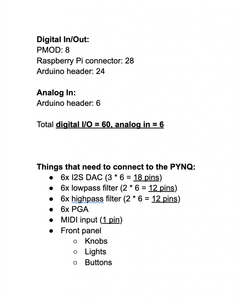
The large number of front panel interfaces combined with six DACs and other various peripherals means that our FPGA board (PYNQ Z2) will basically have 100% I/O allocation. We thought it would be smart to plan ahead and start mapping out which I/O will be used for analog, digital, serial, etc to ensure that our board is sufficient. As per the Gantt chart, we are almost exactly on-time.

