Team Status Report for 2/26/22

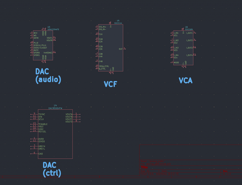
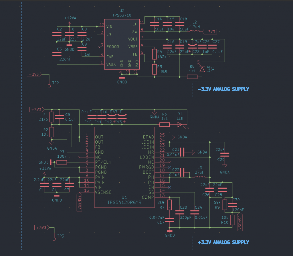
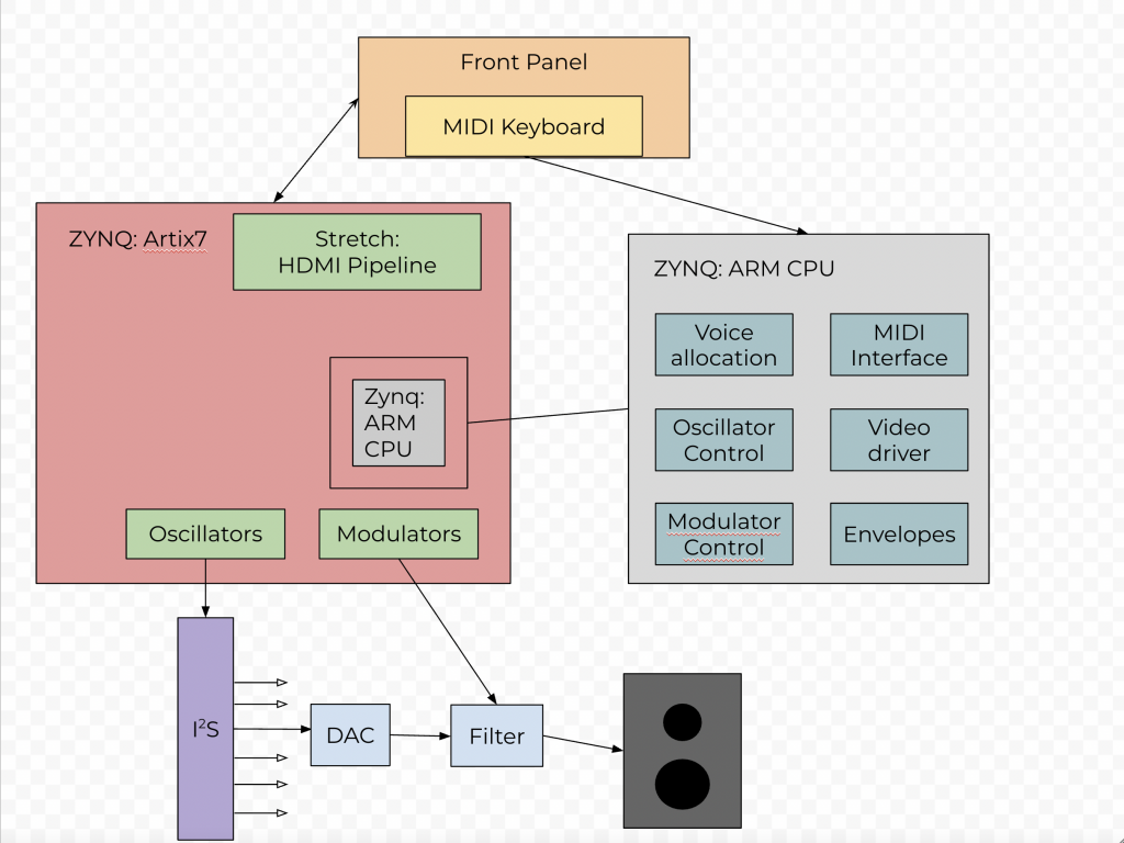
At this time, we have a clear path ahead of us for creating the PROGNOSTICATOR-6. We made changes to the original design last week, but we have not altered it again. Since simplifying our design, our greatest challenges seem to be integration and implementing some complex aspects of synthesis. The analog path may be simpler now, but as Sam discussed in the design review presentation, we still must be cautious of generating noise.

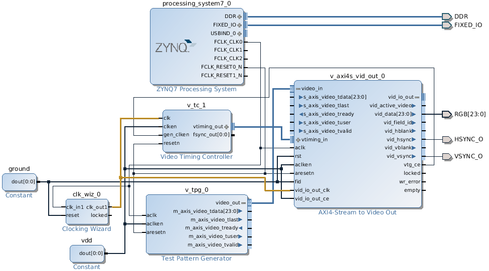
It may be risky to put too much emphasis on the user interface and aesthetics when we have many other elements of the project to consider. What use is a synthesizer that looks pretty, but does not sound good! If there is an overwhelming amount of work on the FPGA, Sam and Graham will need to spend more time on that to ensure that the essentials are completed in time.

Graham’s Status Report for 2/26/22

This week, I wrote a python keyboard program using pygame.midi.  This was easier than anticipated. However, it still exists entirely within my laptop. I attempted to add oscillators and modulators to truly make a digital synthesizer, this is a work in progress. On the ZYNQ, this program can take MIDI input from our controller along with input from encoders. From there, we may add more simple effects in software after we have worked out the complex elements of the synthesizer.

I am still slightly behind on my progress. Last week, I said I would have liked to have some software on the ZYNQ that produces a signal today. I am very confident we can achieve that this week. I am going to put in additional hours over the break to learn to work with Vivado and a Zedboard from the ECE Inventory since Tom will have the PYNQ. This week: I will work with Sam to decide a layout of encoders that makes sense for the PCB, complete the MIDI portion of the synthesizer, and continue to develop the front panel design.

Tom’s Status Report for 2/26/22

This week was mostly research for the video pipeline, and I began working on the Qt application for the linux side of the project.

The video pipeline for the Zynq uses the AXI VDMA core to transfer data out of the framebuffer which is stored in the Zynq’s memory. (The PS and the PL share the same memory.) A video timing controller creates the pulses for vsync, hsync, etc for the HDMI phy.

Lauri's blog | Connecting test pattern generator to VGA output on ZYBO

The main application will run with Qt and draw to the framebuffer. I need to test this, but petalinux (Xilinx’s linux distribution) has finished drivers for the AXI-VDMA system, so as long as I followed the spec correctly Qt should be able to draw to the hdmi output without any real setup. This is tricky and might be very unreliable at first. The Qt application is multithreaded C++ and will do basically all of the complex work for the synthesis, including envelopes, wavetable selection/loading, video output, reading inputs from encoders, and voice allocation.

Graham’s Status Report for 2/19/22

This week, I installed Vivado on my personal laptop and began familiarizing myself with our virtual PYNQ-Z2 board. I ran through some tutorials using Vivado’s behavioral simulation and this week, I would like to see it function correctly on our hardware. It will be very useful to have Vivado available during our biweekly class time!

As a team this week, we narrowed down a specific number and allocation of knobs and buttons for the front panel. There are a few things to still consider, but I went ahead and made a rudimentary CAD assembly for the front panel. This includes 25 knobs, an LED matrix, a screen, and three buttons for choosing patches. It is a rudimentary design, but the dimensions worked out well (2.5×8.5×37.5in) and there is room for adjustment. We will talk about it together this week and I will make the necessary adjustments.

Next week, I will have completed a midi interface in the ZYNQ and have it output a noise or at least the name of a note in text. I am a little behind schedule, but we all had some major design choices to agree on this week. Now that we have done that, I believe we can get really get to work.

Sam’s Status Report for 2/20/22

This week I worked on schematic design and analog filter path design. Our initial project specifications and block diagrams were vague so we worked to solidify those and nail down the specific filter/analog architecture.  To save time and help increase the odds of success we traded the discrete switched-capacitor filter architecture for monolithic voltage controlled filter integrated circuits. We will have a low pass filter with programmable cutoff frequency and resonance that are adjusted proportional to a current value that comes from a control signal DAC. There is also a main (I2S) DAC for the audio path. The output of the filter is then fed into a voltage controlled amplifier before the “line out” jack.

The analog path also requires a very low noise split-rail voltage supply. I designed 2 switching regulator circuit that convert a noisy 12V input to +/- 3.3V (extremely low noise). After some research, I decided to separate analog and digital grounds with an inductive choke to connect them.

This is good progress but is about 1 week behind according to our gantt chart. To rectify this, I plan on having a final filter schematic for next week so that I can begin PCB layout ASAP. In the meantime we can also work on sourcing the parts as we will likely need to order from a few different sources.

Team status report for 2/20/2022

We locked down our synth architecture this week, and decided to switch from a true 6-voiced polyphonic synthesizer to a paraphonic synthesizer. We determined that the io usage and complexity from 6 true analog voices was too complex and risky to implement, and after testing paraphonic synthesizers we determined that the sound was good enough. Basically, paraphonic synthesizers work by using a single global “gate” where the filter envelopes of each note are synchronized, and resets only after all notes are released. This is different than a true polyphonic instrument, but acceptable for playing chords and monophonic melodies

For hardware, this means we’re using one VCF chip, one i2s stereo DAC, and one additional DAC for controlling the parameters of the VCF chip. We may implement two voices in hardware to create a “duophonic” synthesizer, which would allow true stereo patches and a small level of polyphony.

Tom’s status report for 2/20/2022

This week unfortunately was mostly a return to planning to make sure we nailed down the design. I had initially intended to dive into FPGA-land and start bringing up the zynq and the video pipeline. While i was able to synthesize a design for a video framebuffer on the zynq, I haven’t been able to test if it actually works on hardware yet.

Mostly, I ended up focusing with Sam on “knob selection” which meant dialing in exactly what the interface to the synth is, and consequently exactly what features we need to implement on a technical level. We settled on descoping 6 hardware voices in favor of creating a “paraphonic synthesizer” where the gating for all filter envelopes is identical. This is discussed more in the team status update.

I’m currently working closely with Sam to find a way to interface with the many rotary encoders that we use to change synthesizer settings. Due to the chip shortages, the open-source MCU-based designs for this are all unavailable so we’ll have to switch to analog pots or make something custom, since we don’t have enough io to interface all of the rotary encoders with the fpga directly.

My job personally was coming up with this spreadsheet: https://docs.google.com/spreadsheets/d/1Dr5_RnABUDoyzo6D7ym3ToypcFMyjv6tvbP-L7gBcFY/edit?usp=sharing
which details exactly which modulatable features we’re implementing on the synth. This gives us a framework to define requirements precisely for the analog system and how the software needs to be implemented.

Team Status Report for 2/12/22

The project is going smoothly overall and we’ve been working on system level planning like I/O allocation, block diagrams, and front panel layout. Right now it seems like the largest risk that may jeopardize the project is the complexity and number of features that we want to add. A fully featured synthesizer has so many individual features, effects, and subtitles. We have not made any changes to our schedule or planes yet, but may need to slightly reduce scope and define more stretch goals to work on later given extra time.

Initial system block diagram:

Front panel knob planning:

Sam’s Status Report for 2/12/22

Recently I’ve been focusing on two main tasks: programmable analog filter design and FPGA I/O allocation. The hybrid synth requires six analog filter paths with programmable highpass and lowpass cutoff frequencies that are controlled by the FPGA. We chose a switched capacitor architecture in which two MOSFETs are driven with non-overlapping clocks. to emulate a programmable resistor. The topology was selected, components were sized, and a simulation was run to verify the results across the audio frequency range. We will build 12 of these circuits (6 voices x 2 types (high, low pass))

The large number of front panel interfaces combined with six DACs and other various peripherals means that our FPGA board (PYNQ Z2) will basically have 100% I/O allocation. We thought it would be smart to plan ahead and start mapping out which I/O will be used for analog, digital, serial, etc to ensure that our board is sufficient. As per the Gantt chart, we are almost exactly on-time.

Tom’s status report for 2/12/22

This week I worked on the toolchain for the Zynq. I downloaded vivado and started working on the hdmi pipeline as a good test of the toolchain. We started knob allocation and a creating a list of modulatable signals. I personally got the zynq to boot and finished a detailed block diagram for the system. Coming up, I want to actually test the hdmi pipeline and start working on the software including voice allocation, pseudo code for wavetables, and envelope code.