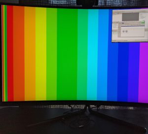
Since the 13th, I have made some major changes to the PPU task schedule. Due to some design decisions made in the design review report, and most notably our decision to replace our DRAM interface with an M10K VRAM, I have decided to combine the Tile-Engine implementation tasks into a single task, and add several new tasks relating to the PPU FSM.
Firstly, due to the new PPU FSM design, I was required to re-implement the HDMI Video Timing. This effectively combines the HDMI Video Output and Video Timing Generator blocks into one custom block. The reason was to gain better access to important signal timings such as DISPLAY, or VBLANK, as well as to read and swap the new row buffer.

The row buffer currently initializes with a test pattern (shown in the image above). The new HDMI Video Output block reads this buffer for every row. The goal (due next week by Wednesday) is for two row buffers to be swapped in and out, and the PPU-Logic (Tile Engine, Sprite Engine, and Pixel-Mixer) will fill the buffer not in use. The important progress made here is that the HDMI Video Output automatically fetches pixel data in the row, extracts an address from that pixel data to a color in the Palette RAM, and then reads from Palette RAM to obtain the final color. This sequence occurs 320 times in a row, with each result held for an additional 25MHz clock cycle to upscale to 640px resolution.

The next task I completed was the Double-Buffered VRAM implementation. Our VRAM consists of two identical VRAMs, one which is used by the PPU during the DISPLAY period, and one which the CPU can write to during the DISPLAY period. The VRAMs must be synchronized at the start of the BLANK period so that the CPU can write to a VRAM which accurately reflects the changes it has made since the previous frame. The Double-VRAM was implemented using a SystemVerilog Interface to manage all 36-per-RAM signals. The reason there is such a large number of signals is because we use the native M10K dual-port RAM configuration, which allows for an extra port for every signal, and our VRAM is split into 4 segments (each with their own controls). The VRAM Sync is implemented in a new block called VRAM Sync Writer. The VRAM Sync Writer controls all ports of each dual-port VRAM in order to speed up the copying.
Test-benches and simulations with RAM models provided by Altera were used to verify that the synchronization works. I instantiated RAM modules with pre-initialized data, sent the start signal to VRAM Sync Writer, and compared the resulting RAMs using ModelSim’s interface.
Lastly, I’ve implemented the PPU FSM and CPU write. No physical hardware tests have been done with respect to CPU write, but a dummy CPU module was used to write values to each VRAM location, and the results were confirmed via ModelSim. I’ll hopefully finish this after this report is due tonight, and get started working on the Tile-Engine tomorrow.
I am almost on track with the progress expected on the schedule, after communicating with Andrew, I’ve decided to push back the final PPU Kernel Module until after the interim demo and focus on a user-space (non-kernel-module) software driver instead.
