
Shiva’s Status Update for 04/26
This week, I worked on the final presentation and collected more data to help Udit and Rhea refine the multilateration algorithm:
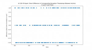
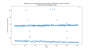
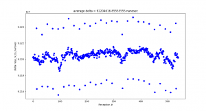
At Tamal’s recommendation, I let the anchors ‘warm up’ by running them continuously for at least 30 minutes prior to testing. This contributed to a significant reduction in timestamp reception variance in real-world testing, sampled below:
Test 10 — Stats of Direct Difference in Synchronized Reception Timestamps between Anchors that are equidistant from Tag, in Nanoseconds:
Mean = -0.11842105263157894,
Median = 0.0
St. Dev = 0.8105733069084967
—-
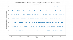
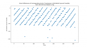
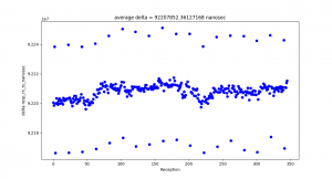
Test 11 – Stats of Direct Difference in Reception Timestamps between Anchors that are equidistant from Tag, in Nanoseconds:
Mean = 0.3470031545741325,
Median = 0.0,
St. Dev = 1.4427340556024508
We are on schedule for our presentation this week and demo + report next week. Next week, I will work on the report and, if needed, scale up the experiment for more anchors.
Shiva’s Status Update for 04/19
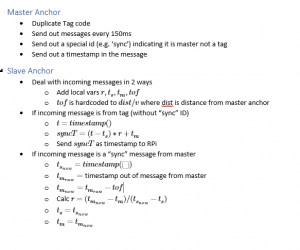
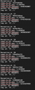
This week, I collected more experimental data for Udit and Rhea to use in tuning the multilateration algorithm. I implemented a time-sync algorithm in the Decawave chips that uses a master chip which periodically broadcast its own timestamp, which the slave anchors adjust their own clocks in response to, before transmitting pulse reception timestamps to the Raspberry Pi.
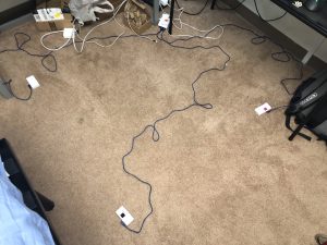
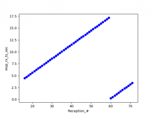
I also assembled an experimental setup to test the algorithm, setting up the tags and anchors in a 1×1 meter square. I set up two slave anchors that broadcast the time of pulse reception to the Raspberry Pi server, a master that only broadcasts a timestamp, and a stationary tag that broadcasts its ID. The setup was meant to keep both anchors 1 meter away from both the tag and the master simultaneously.
Our progress is on schedule for a demo this Wednesday. Udit and Rhea have been making substantial progress towards an effective multilateration algorithm with imperfect data, and I have established a consistent workflow for graphing and collecting timestamp data from multiple anchors and multiple tags simultaneously.
This week I will perform any final tests that Udit and Rhea need to fine-tune the multilateration algorithm, and then we will demo on Wednesday.
Team Status Update for 04/12
The team’s progress is steady. It was disrupted slightly by the midsemester demo, but Shiva has made good progress in collecting real-world data from the Decawave tags through the Raspberry Pi. Meanwhile, Udit implemented an ideal-data multilateration program that was accurate to within one foot as desired by our original implementation metrics. He and Rhea are collaborating on the imperfect-data program now.
The most significant risk to the project is on Shiva’s end. He needs to investigate the inconsistent transmission and reception timestamps generated by the Decawave hardware. In the worst case however, the team can use the imperfect data that he already collected and use that in Udit’s multilateration program.
Neither the design nor schedule of the project have changed significantly since last week.
Shiva’s Status Update for 04/12
This week was all about collecting experimental data for Udit’s simulator.
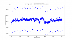
At the beginning of the week, I connected the Decawave TAG to the Raspberry Pi and logged timestamp data from the chip on the Raspberry Pi. I also wrote a Python script to parse logged data from the tag and graph the periodicity between its transmission pulses:
I observed a consistent pattern of timestamp outliers. Additionally, even though the tag was programmed to only pulse once every 100 million nanoseconds, the average time between pulse receptions was 92 million nanoseconds. At first I thought the issue might be on the anchor’s end. However, when I logged the transmission times directly from the tag, I observed nearly identical results:
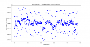
I am not yet sure what the source of these problems are.
One source may be the Decawave’s API, which zeros out the low 8 bits of its internal clock automatically to store the timestamp in a 32-bit format. This means that the time counter is only accurate to within 8 nanoseconds of the true transmission time. This problem may be compounded by the Decawave clock’s low rollover time — the system clock is only 2^40 bits long, and each bit of Decawave time is about 15.65 picoseconds of real time. This means that the clock zeros itself out every 17.2 seconds
To investigate further, I wrote a script to read the tag’s data in real-time and insert the Raspberry Pi’s own system clock time into the log to compare. However, this script does not work yet; a bug that I think is caused by non-atomic read/write operations means that the script prints the Pi’s system clock into the middle of the Decawave log, scrambling the log results and making it impossible to parse consistently.
In the second half of the week, I tried modifying an example TDOA tag code provided by Decawave to communicate with the anchor code I had written, but had no success.
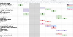
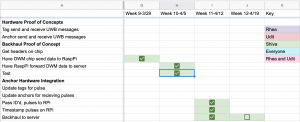
This is a bit of a switch-up on the Gantt chart. Originally, I was going to have the Raspberry Pi forward timestamp data to the multilateration server and test out the program:
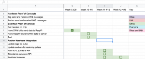
However, we shifted gears to accommodate our midsemester demo. Udit implemented an ideal multilateration algorithm to show for the demo, which did not need that info. So I worked on passing the tag and anchor IDs to the Pi and timestamping the pulses directly on the Pi.
Next week, I will continue investigating these problems, fixing the bugs in the RPi timestamp program, and working with Udit to pass realistic timestamp data to his multilateration program. Since I got some of next week’s work done this week, I am still on schedule.
Shiva’s Status Update for 04/05
This week, per our revised Gantt chart, I was able to send data from the Decawave chip to the Raspberry Pi over UART. Although I also wanted to transmit data over SPI, the SPI functionality in the Decawave chips were poorly documented. Their guide referenced a test program that was not actually included in the Decawave firmware and software bundle download. Thus, after conferring with my team, we decided to stick with UART over USB rather than waste time fiddling with SPI.
This week, now that I’m able to get correct timestamp data, I will be setting up a system of multiple Raspberry Pis attached to Decawave chips and collecting experimental data on metrics that can be fed into the simulator Udit and Rhea are developing.
Our team’s progress is still on schedule.
Shiva’s Status Update for 03/28
At the beginning of the week, I worked on implementing an ideal multilateration algorithm in Python, based on https://en.wikipedia.org/wiki/Multilateration#Cartesian_solution_with_limited_computational_resources.
After Wednesday, based on Tamal’s concerns with our hardware implementation, I switched gears. I passed the multilateration software over to Udit for him to finish implementing and returned to the Decawave hardware to identify key metrics and details of how it tracks time.
From Wednesday through Saturday, I verified the conversion rate of Decawave time units to real-time seconds (1 DTU ~= 15.65 ps); identified the issue of timer rollover (the Decawave chip timer rolls over every 17.2 seconds), fixed the TDOA software so that the anchor now correctly reads the timestamp of pulse reception; implemented time conversion so that the software can display and log the timestamp in seconds, microseconds, and nanoseconds; and wrote a Python script to graph a single anchor’s measurements of when it receives pulses from a single tag.
Progress is still on schedule, though we’ve had to change some responsibilities around due to the COVID-19 crisis. In particular, Rhea and Udit are now working on the multilateration software. For next week, I will verify the accuracy of the Decawave chip timestamps, then collect sample timestamp measurements using the Decawave chips at various distances to plug into Udit’s simulator.
Shiva’s Status Update for 03/21
This week, I successfully completed the deliverables E2E Blink Delta Proof of Concept and Scaled E2E Blink Delta Proof of Concept.
Technically, I’m still one week behind per the details of the current Gantt chart because Rhea was supposed to work on Scaled E2E Blink Delta Proof of Concept, but COVID-19 has forced us to rescope and we will be modifying the Gantt chart to reflect this.
Personally, I still plan to complete the E2E TDOA deliverable. I want to implement a functional multilateration algorithm in Python by the second week of April.
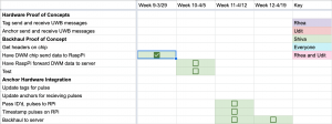
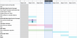
Gantt chart:
Shiva’s Status Update for 03/15
In the week before spring break, I started working on the TDOA code for the E2E Blink Delta Proof of Concept milestone in our Gantt chart. I spent the first half of the previous week reading, documenting, and understanding the existing Decawave API, and then the second half of that week writing my own TDOA solution. Unfortunately, my TDOA code was buggy for one reason — I completely did not think about the fact that TDOA does not use timestamps in the same way that Two-Way Ranging does, and tried to write my code using TWR’s mechanism as a baseline.
As a result, I am currently a week behind schedule. I will be using my slack time this week to remedy that and rewrite the TDOA code accordingly. Whereas previously I was trying to send the tag’s timestamp and only test on a single anchor, now I am going to rewrite the tag code to only send its ID and rewrite the anchor code to only log the time when it receives the ID pulse. I will then run this code with two anchors to check that they can both correctly receive the tag’s ID.
Luckily, the need to work with multiple anchors also dovetails into my next deliverable: Scale E2E Blink Delta Proof of Concept. This deliverable requires multiple anchors to identify the tag, which is inherently required for a functional TDOA system. As a result, I aim to accomplish both E2E Blink Delta Proof of Concept and Scale E2E Blink Delta Proof of Concept over the next week.
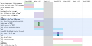
Gantt Chart:
Team Status Update for 02/29
We changed our order for implementation but no main change to design. We will pressure time sync with simplest solution (just raw clock in RPi) before trying more complicated solutions like TCXOs or centralized clock with a wire connecting to each anchor.
The change was necessary because we were struggling to make progress on implementing the chips in same fashion before paralleling other tasks. And looks like we finally have that (even if we don’t fully understand the entire API yet)
Achieving accurate time sync remains a problem since we can only experimentally verify what will work and not plan for it.
We plan to ameliorate those risks by trying to start working on it next week (earlier than scheduled)
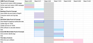
Here is our updated Gantt Chart.
Our main success in the past week was a functioning TWR demo, as seen in Shiva’s Status Update for 02/29. We also have to get a test in ANSYS on Monday though.