20 April
Team:
The team is on pace to finish our minimum viable product (MVP) before our final in-lab demo this upcoming week. We ran into some problems with the motors and the power supply, and ended up opting for a power supply with less voltage and current to ensure safety. As of now, the cube state module can properly read the cube and pass the cube string into the Two-Phase solving algorithm. Lily and Sam are still working out some of the kinks for the Beginner’s Method, but this isn’t as much of a priority because Cubr can still work without it. From the Two-Phase algorithm, we can properly generate a solution string and pass the input through the serial monitor to the Arduino. The Arduino parses the string and turns the respective cube faces accordingly.
We printed our final coupling arms and finally have enough for each motor. With all of this working, the final component is the housing. The team has decided to design, laser-cut, and assemble a housing from clear acrylic. JT and Lily designed and measured the right specifications for the housing. Lily and Sam actually created the laser-cutting guides in Adobe Illustrator and were able to laser-cut the housing in preparation for assembly in class Monday. The team is right on track with the exception of some debugging in the Beginner’s Method solving algorithm. We plan to physically solve a cube by next Wednesday. If all goes to plan, we’ll be fine-tuning and cleaning up our code and wiring for the final demonstration.
JT:
This week has been a scramble to try and achieve the basic MVP for the final in-lab demo next week before our final presentation. The core of Cubr works, it just lacks a housing to actually hold the cube. All this week I’ve worked with Sam and Lily to plan a basic housing structure for the robot. After going over many options such as, woodcutting, 3d printing, and laser cutting acrylic, we’ve opted for the last option. We plan to laser cut clear acrylic to hold each of the motors. The housing is a basic cube inspired shape designed to fit like a puzzle. Our biggest concern was making sure we had the right measurements and a method for getting all coupling arms properly aligned to the center pieces of each cube.
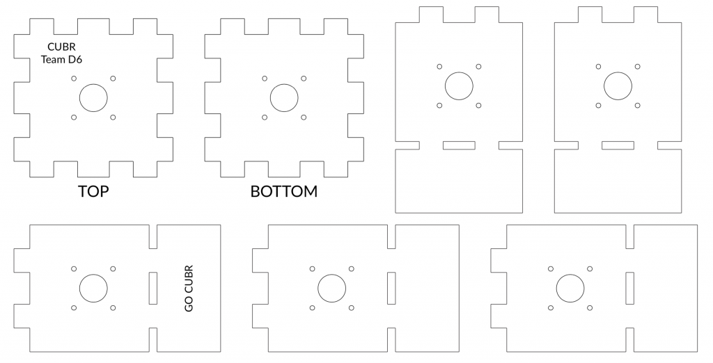
Lily and I took measurements of the cube, stepper motors, and coupling arms. I was going to be out of town this weekend, so we wanted to have all the measurements and design flushed out before I left. You can find the basic schematics in Lily’s section. In essence, we only need to design two parts as the rest can be duplicates. We will have four identical pieces for the side frame and two identical pieces for the top and bottom. The idea is that all the pieces will attach like a puzzle one by one. This allows us to properly align each side of the cube one piece at a time. We’ll also be mounting the motors to the acrylic through the provided mounting holes on the motors to avoid the need for special mounting brackets.
I believe we’re on track to assemble this rough cut of the housing. Just in time for our in-lab demonstration on Wednesday. If all goes according to plan we should have at least two weeks to clean up and fine tune the rest of our project before the final demonstration.
Lily:
JT and I carefully took measurements of the motors, cube, and coupling arms for our preliminary housing designs. We opted for acrylic material so that the final housing will be see-through (so we can see the cube being solved!) and so we can mount the motors directly onto each acrylic panel instead of purchasing and using mounting brackets. We opted to design two different pieces, one for the top and bottom panels and another for the side panels of the housing so that pieces can attach to one another like a puzzle. In addition, we included pilot holes around the motor for easy mounting and a bigger hole for the motor and coupling arm.
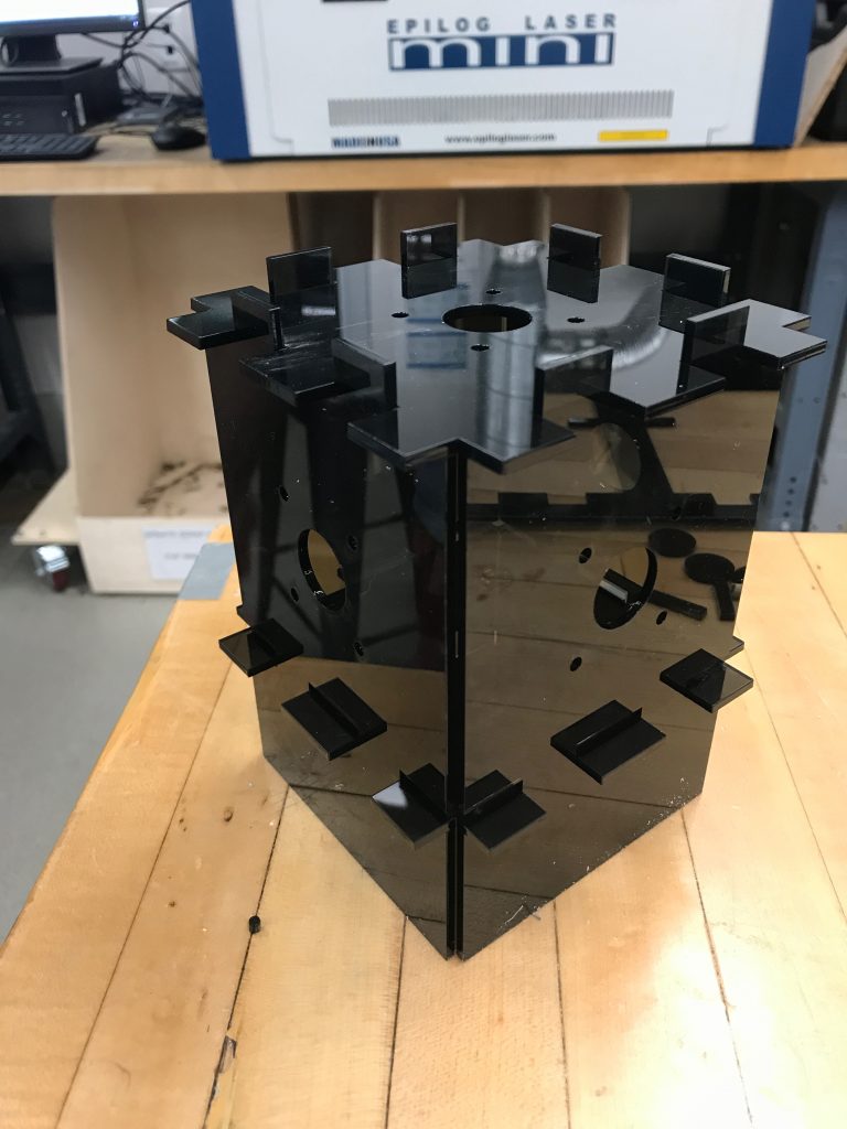
Later, Sam and I solidified the housing design in Adobe Illustrator and successfully laser-cut the housing panels. The makerspace only had 1/8″ dark (but mostly see-through) acrylic sheets available, so the current housing will not be our final one. We plan for our final housing to be constructed out of 1/4″ colorless and clear acrylic for stability and visual presentation. So far, all of the panels fit together well, except for the bottom piece due to the slots in the side panels having a height of 1/4″ instead of 1/8″. We have some issues with stability, as was expected with the 1/8″ thickness, and, in the meantime, we plan to remedy this by using rubber bands to hold the panels together. We plan to mount the motors by Monday for testing.
Sam and I have been working on debugging the sublayer algorithms in the Beginner’s Method so that all of our unit tests will pass. Consequently, the top layer algorithms are still a work-in-progress. With the two weeks remaining, I am confident that they will be verified and debugged with Sam’s help in time for the final demonstration.
Sam:
This week we begun work on the housing by first finding the actual measurements of the motors, the cube, and the coupling arm. We then designed our housing on paper by figuring out how the different sides of the housing will lock together. We are using ¼ inch acrylic so this was taken into account in our design. We all built a preliminary design of the housing in lab and Lily and I further iterated over the design as we kept finding minor problems with our original design. The design for the housing has 6 sides. We designed 2 different pieces. One for the top and bottom of the housing and one for the 4 sides. We iterated over our designs by using scratch paper and finally implementing the design with exact measurements in Adobe illustrator.
With the blueprints in illustrator, we are now ready to get our design laser cut and see how our housing builds physically. Lily and I went to the makerspace and laser cut the design. They only had ⅛ inch acrylic so we may have to print again with ¼ inch if it is not sturdy enough. Building the structure, it wasn’t as sturdy as we’d hope but there are many avenues for us to make this structure sound. In the upcoming week, I will work to implement the housing so that our motors are sturdy in the structure. I will also make the appropriate adjustments to our housing design in case we do need to change some dimensions. We are on track and hope that we’ll have a solid demo for Wednesday. Go Cubr.
0 Comments