6 April
Team:
This week was demo week and in our demo we showed 2 things. The first thing we showed was cube state detection from beginning to end which outputted the solution string. The next thing we showed was our motor successfully turning 2 faces of the cube. The most significant risk for the project at the moment is correctly creating the housing so that the motors are completely perpendicular to each other and snug enough so that there are no minor offsets with each turn of the cube face.
A problem that arose in the demo was when we were manually holding the center pieces of the cube and the motors while the motor was turning faces of the cube. We didn’t hold the motor perpendicular to the cube which caused some turns to be overshot. This is not unexpected however, we put in a buffer into our schedule to allow for this so we are still on track. We have partitioned time for Cubr to making the housing properly. We are currently on track.
JT:
This week was a really reassuring week for my portion of the project. With Sam done with the cube state detection and Lily still working on the solver, I needed to be able to get multiple motors working and actually turning the cube for our mid point demo. In the previous weeks, I’ve been solely working on a single motor. I feel like I’ve learned enough about the single motor subsystem and this week I started to progress towards operating multiple while still maintaining the same level of safety. I’m properly setting up the potentiometer on our motor drivers to ensure we’re giving minimal current to the motors. The motors can receive higher current, but to be safe I’ve been working on the lower end of its range.
For the midpoint demo, I was able to successfully control two motors of the solver that could actually turn the cube at full load. You can see a gif of the solver turning the cube under the team section. Knowing this, the rest of my work should be cleaning up the wiring and setting up the rest of the motors correctly. Next week, I’ll aim to have all six motors working in conjunction. On top of this, I want to cleanly organize and wire all the components so it’s easy to move and see what is connected to what for debugging. As for time, we’re probably about a week behind schedule, but we still think it’s possible to complete our project within the next two weeks max. I’d like to have the robot completely wired and functional with serial input by the end of next week. If all goes according to plan, I can solely worry about creating a housing.
Sam:
We had a demo this week so I spent time physically setting up the cube state detection portion of our project. The demo was successful and one important inquiry that came out of it was about scanning the center pieces. We’ve 3D printed the coupling arms that connect to the centerpiece once you take the cap off. So we are now thinking about leaving the centerpiece caps off and simply coloring what’s under the caps so that in the pipeline of our project we don’t have to manually take the caps off. This will save some time in our process and ultimately make the project more seamless.
This past week, I also worked on the serial communication with PySerial and have been talking with JT to see how to integrate our two parts. I have spent the past week learning more about the work both Lily and JT have been doing. JT took me through how exactly the Arduino is controlling the motors via the circuit schematic. We also discussed how we plan to hook up the six motors in parallel.
I also talked with Lily about her progress on the solver and how exactly she is representing the cube and what she has done and needs to be done. These technical chats with JT and Lily were very helpful for my understanding of the full stack of the project and gauging the timeline of how we are doing as a group and what needs to be done. We aim to make great progress this week before Carnival to put us in a good spot next week. Go Cubr.
Lily:
At the beginning of the week, the print job for our preliminary 3D printed coupling arms finally completed, so I worked on removing the supports and filing down areas on the coupling arms until they fit our motors and our cube center pieces in preparation for our preliminary demo. JT and I managed to successfully control two arms to turn different faces of the cube. In the upcoming weeks, we will be working together on designing and constructing the housing. I will also assist JT with wiring up the rest of the motors and ensuring our current loads for each motor in parallel does not exceed their current ratings.
Sam will be assisting me with the rest of my solver module in the coming weeks. I have finished the solving algorithms for the first layer, as seen below.
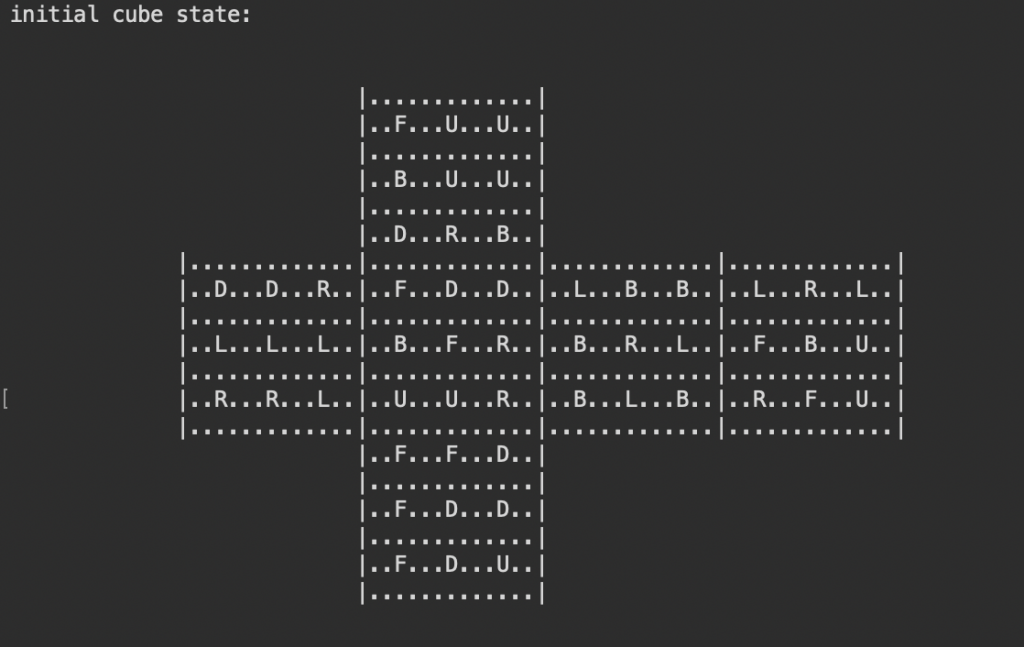
In the first layer, the solving algorithm aims to complete a so-called “white cross” (since the typical denotation for the Down face is white). As one can see in the cube’s initial state (an example of what would be received from the cube state detection module), the Down face of the cube has the ‘color’ D in the top right, center middle and middle right, and bottom middle facelets. The “white cross” state aims to have D in the middle columns and middle rows of the Down face. In addition, the oriented “white cross” pieces must correspond to the center pieces of the second layer (i.e. the edge piece DR must be placed such that the D facelet is within the Down face and the R facelet is within the Right face).
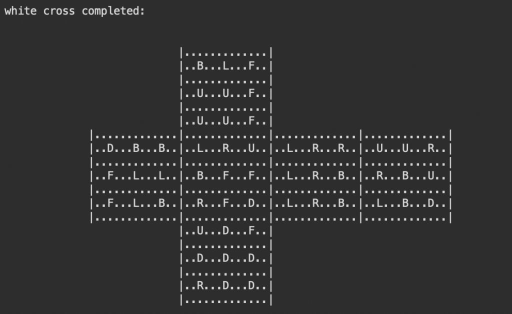
Above, one can see that the cube has reached the correct “white cross” state. To complete the first layer, the “white corners” must be oriented such that the corners correspond to the middle layer center pieces as the edge pieces were required in the previous state (i.e. the edge piece DRB must be placed such that the D facelet is within the Down face, the R facelet is within the Right face, and the B facelet is within the Back face).
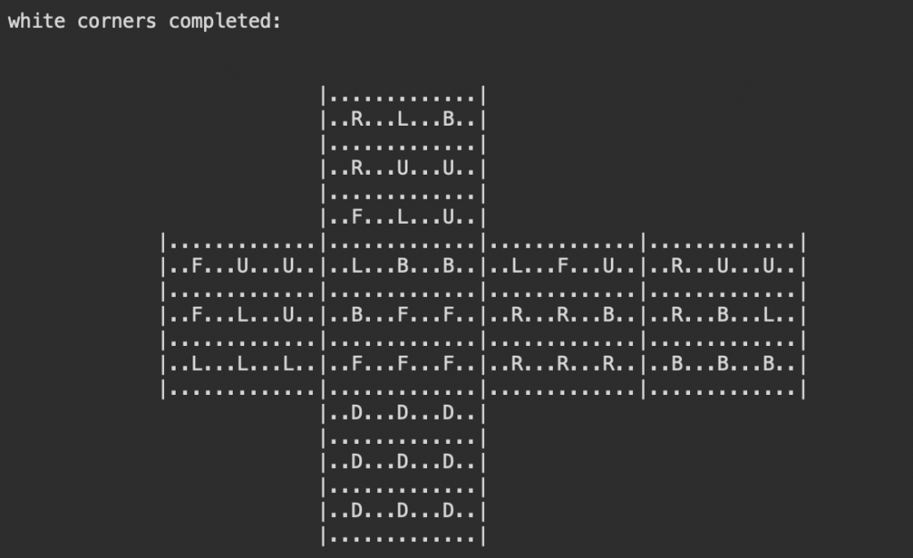
Finally, the first layer is completed. As one can see, the Down face is fully oriented with D facelets while the layer above is as follows, in correspondence with the center pieces in this 2D orientation:
L L L F F F R R R B B B
For this initial cube state, there are only 27 moves to reach a fully solved first layer. With this in mind, I am hopeful that our solver will find a solution under a few hundred moves.
In the next step, the rest of the middle layer pieces must be oriented before completing the top layer. After some discussion, JT and I agreed that the top layer can be solved in a less naive method than the Beginner’s Method, which permutes the top layer until it eventually reaches the solve state, for a smaller resulting solution string. Invented by Professor Jessica Fridrich, the Fridrich Method or (commonly known as) the CFOP Method (Cross – F2L [First Two Layers] – OLL [Orient Last Layer] – PLL [Permute Last Layer]) is one of the most popular solving methods for the speedcubing sport. The steps related to the top layer are the OLL and the PLL. There are 57 different orientation cases for OLL to orient both the edges and the corners of the top layer at once. There is a simpler sub-method known as the “2-Look OLL” of which there are 10 different orientation cases and orients edges separately from the corners. The last step is PLL, in which there are 21 cases. JT and I introduced the CFOP Method to Sam this past week, so the approach for virtually solving the top layer will await further discussion with Sam and his familiarity with the CFOP Method (and after the completion of the second layer). With Sam’s assistance, I’m confident that we will finish the solving algorithms soon and with plenty of time for integration testing between the modules.
0 Comments