David
This week I worked designed the PCBs for the TP sensor and TX/RX boards.
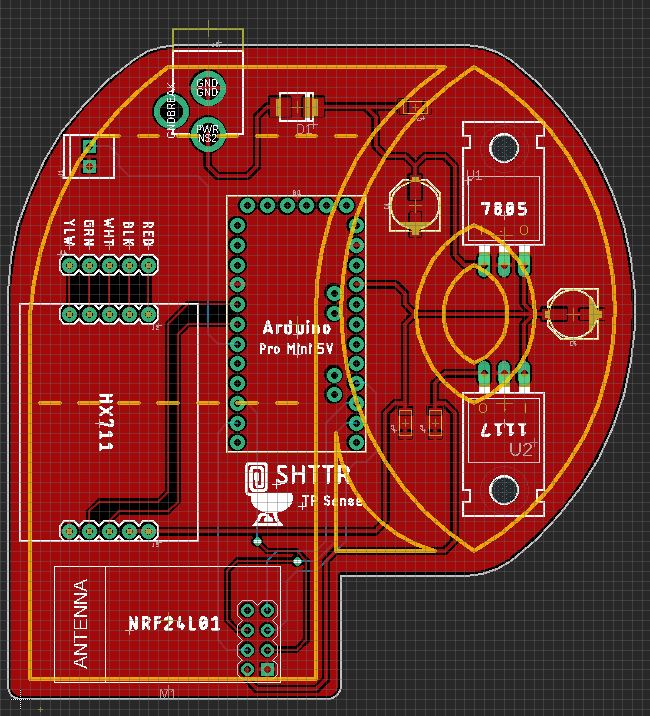
First, the PCB for the TP Sensor had to accommodate the Arduino Pro Mini, as well as the socketed HX711 Load Cell Amplifier board, and the NRF24L01 RF Communication Board. Due to the 5V nature of the Arduino and HX711, combined with the 3.3V operating voltage of the NRF24L01, power regulation circuitry had to be designed to step down the input voltage to both 5V and 3.3V.
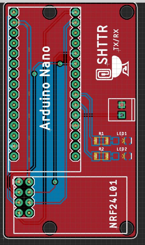
The TX/RX board was a bit more simple but had its own design considerations to be multi-purpose. The form factor of an Arduino nano was chosen in order to provide easy USB communication with the Pi, and cheap cost of materials. The board is designed to be multi-purpose, with the screw terminal only populated for the Door Latch Sensor, and the LEDs/resistors only being populated for the simulated flush valve.
Given the changes to the schedule to accommodate the pivot to RF vs RFID, I was not on the schedule at the beginning of the week, but with the boards designed, I am now back on schedule (the new schedule).
Next week, I hope to:
- Order the PCBs and Parts
- Assist James in developing the RX/TX Firmware
- Begin designing the final enclosure for the TP Sensor
Team Update
This week we overhauled the system design, pivoting to RF instead of RFID. The updated block diagram was detailed in last week’s update. This week we updated the Gantt chart, and our schedule still looks very feasible. Here is the updated Gantt Chart (also linked for download):
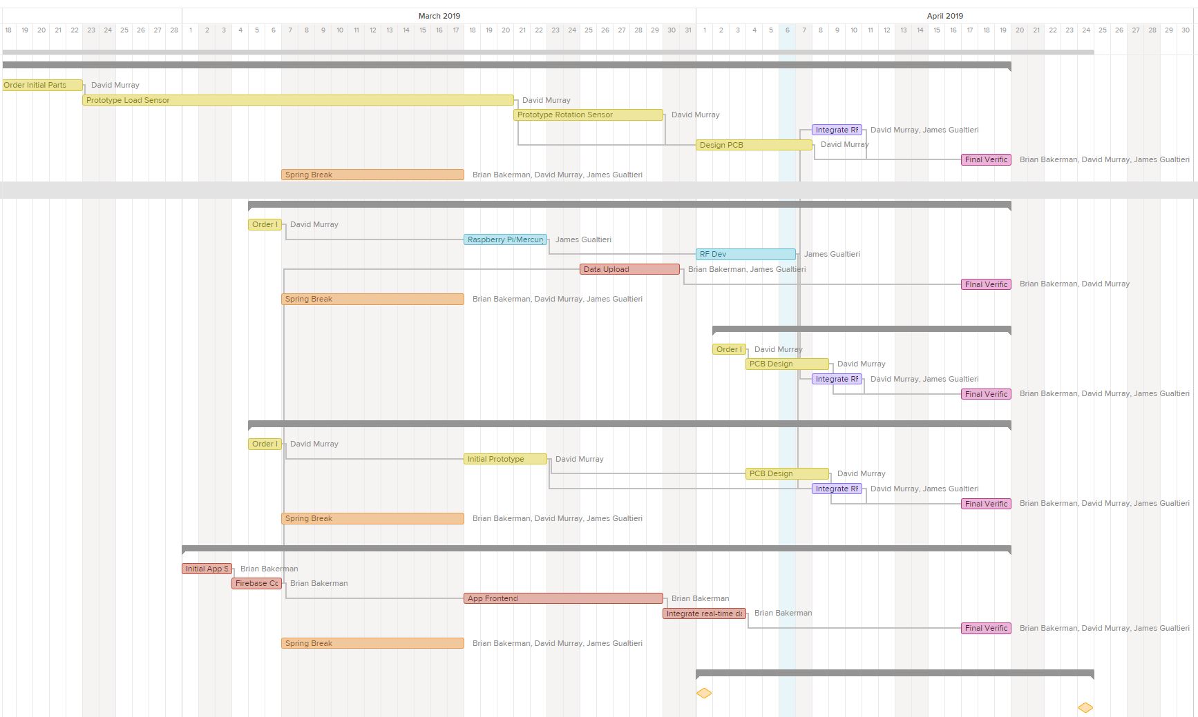
SHTTR Gantt
We still have a decent amount of buffer time built in and we are not concerned with where we are. Given that the NRF24L01 chips were tested to work earlier this week, the communication is definitely feasible.
0 Comments