
Atharv Kashyap‘s Status Report for 10/03/2026
This week I moved from planning the signal-processing pipeline to building it. I implemented the first Python version of the SynapSys decoder, including bandpass/notch filtering, CCA, three-command classification, and rejection logic. I kept the main parameters configurable so we can easily change things like sample rate, window length, harmonics, and thresholds once we start testing with our own hardware. The next step for next week will be converting this to C/C++ using tools like Claude so that it runs on the ESP32 as well as testing on real datasets to make sure all parts are working (this was only tested this week with synthetic data).
For now, the classifier compares the EEG against 8.57, 12, and 15 Hz references and gives each one a CCA score. The highest score is the predicted command. I also added confidence and winner-vs-runner-up margin checks so the system can eventually reject unclear inputs instead of always forcing a YES, NO, or HELP result. This is exactly what we documented for our design report and what Theodora presented last week. I have not chosen the final thresholds yet because these need to be determined from our own calibration recordings.
Here is a screenshot of the repository:
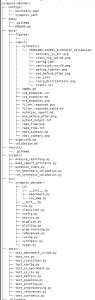
I (using Claude) also wrote automated tests for all the different coding stages. Right now, 193 tests pass with no failures. These cover the reference signals, filtering, CCA calculations, classification/rejection logic, synthetic EEG generation, metrics, and data loading.
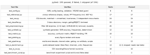
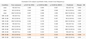
Before moving to real EEG, I tested everything using synthetic data where I already knew the correct answer. I generated fake EEG containing 8.57, 12, or 15 Hz signals, then added noise, drift, 60 Hz interference, and differences between channels. For example, a synthetic 12 Hz trial should produce the largest CCA correlation for the 12 Hz reference rather than 8.57 or 15 Hz. There was no noise in these data points so obviously I expected a big spike and strong correlation scores. This was just to test if the processing worked. I repeated this for all three commands.
Example CCA output:
I cannot upload thet tests.csv files due to security reasons on WordPress blocking me.
For clean signals, the correct CCA reference clearly gives the highest score for all three commands as expected.
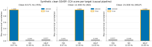
I then added much more noise and also tested pure noise, off-target signals, and ambiguous mixtures. The correct reference still tended to score highest for valid trials, but the scores became closer together as the inputs got worse. This was useful because it showed exactly why we need rejection logic instead of just picking the largest score every time.
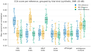
Python is being used as our reference implementation and analysis environment, while the final filtering, CCA, and rejection logic will run in C/C++ on the ESP32-S3.
Schedule
I am on track right now. Next week is going to be busy because we also need to finish the design report and get the PCB ready to send out.
Deliverables for Next Week
Finalize and send out the PCB design (will help with layout and BOM finalization), test CCA against Wang et al. SSVEP dataset and once it works, port the Python to C/C++ for the ESP32 and finish my parts for the design report.
Atharv Kashyap‘s Status Report for 09/26/2026
I was sick this week and missed Wednesday’s class, as well as some targets our team had set between ourselves for the design proposal. This caused us to be a little rushed at the end of the week before slides and this report were due. I did not communicate this well enough to my team, so one thing I need to improve is communicating delays earlier instead of waiting until a deadline has passed.
My planned work also changed after our discussion with Prof. Byron Yu. He brought up several valid concerns regarding what were controlled and confounding variables in the experimentations we planned to build our model around. We realized that public SSVEP datasets were collected under specific experimental conditions that do not necessarily match our electrodes, hardware, display, or environment. Instead of relying on those results to validate our system, I developed an initial plan for collecting our own data as written below:
- Keep electrode placement, reference, viewing distance, screen brightness, lighting, sampling rate, and trial duration consistent. Here are some preliminary numbers. For our initial testing, we will use O1, Oz, O2, and POz over the visual cortex with the same reference and bias placement (earlobes) for every session. The display will be fixed at 60 Hz, approximately 60 cm from the user, with constant brightness and room lighting. EEG will be sampled at 250 Samples/sec and processed over 2–3 second windows. Each command will initially be tested over 30 randomized trials, split into blocks of 10 with short breaks to reduce fatigue. These values will remain fixed during testing so changes in classification performance can be attributed primarily to the EEG response rather than changes in the experimental setup.
- Use our three stimuli at 8.57, 12, and 15 Hz with the display fixed at 60 Hz. These numbers have changed since before. The reason was that studies showed SSVEP responses are strongest at the stimulus frequency and can also appear at its harmonics, so we wanted frequencies that were sufficiently separated without one being a simple harmonic of another. We also wanted frequencies that our 60 Hz display could reproduce exactly using integer frame periods. Our current set uses 7, 5, and 4 frames per cycle, giving 8.57, 12, and 15 Hz. This keeps all three targets in a commonly used SSVEP frequency range while avoiding direct harmonic overlap between our three fundamental frequencies.
- First test each frequency individually and verify that it appears in the measured EEG.
- Then collect randomized YES/NO/HELP trials in blocks with rest periods.
Finally, I completed a working stimulus renderer for YES/NO/HELP. It generates the three frame-locked frequencies, checks the display refresh rate (so it was not hardcoded to my Macbook, for example), logs the frame timing, and gives us an interface for both the presentation and later data collection.
Below is a screenshot of the interface:
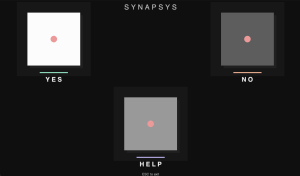
AI, specifically Claude Opus, was used in its creation, as well as setting up the initial repo with README, pyproject, various pytests, and general documentation.
Schedule
I am behind schedule, in this course and my others, due to being sick and because the experimental approach changed this week. I completed my other course’s labs early so I can dedicate more time to the project on Tuesday and Thursday’s dedicated lab time next week to catch up.
Deliverables for Next Week
I plan to implement and test the initial CCA classifier, help write the design report, and define quantitative requirements for classification/rejection and PCB testing. I will also finish documenting and testing the stimulus renderer so it is ready for our eventual EEG experiments. As a team, we plan to finish the schematic/design review, continue PCB layout and component choices, and move toward the first PCB fabrication order.
Atharv Kashyap‘s Status Report for 09/19/2026
This week I focused mainly on the signal-processing side of SynapSys and on researching existing SSVEP systems as well as how they are decoded so that we can make informed decisions before implementation or further planning. I spent the time doing literature review, researching datasets, doing component research, and BOM development.
I read several papers on SSVEP-based BCIs. Below are the ones that stood out and my reflections about them:
Neural Decoding of EEG Signals with Machine Learning: A Systematic Review
This paper clarified the broader EEG pipeline where it showed how to separate preprocessing, feature extraction, and classification. It taught that alpha brain waves occupy 8-13 Hz which we will focus on for SSVEP. SSVEP is steady-state visually evoked potential where lights flickering at different rates as visual stimuli cause our brain to generate an electrical signal.
Low-cost Circuit Design of EEG Signal Acquisition for the Brain-computer Interface System
This was the perfect EEG paper which showed the breakdown of the circuitry we will build into the following sections: RFI filter, protection circuit, main amplifier, band-pass filter (active low-pass and high-pass filters), notch filter, and isolation circuit. I believe this paper will be key for the designing of our PCB and we might follow it almost exactly.
I also investigated several open SSVEP datasets so that we can build and validate the decoding software in parallel while our PCB is still being designed. This is important to the schedule because signal-processing development does not need to wait for fabrication.
Here is the first one: An open dataset for human SSVEPs in the frequency range of 1-60 Hz and here this is the download link
It contains recordings from 30 subjects, 64 EEG channels, stimulus frequencies from 1–60 Hz in 1-Hz increments, two modulation depths, and a 240-Hz stimulus display. It also provides both continuous BIDS recordings and stimulus-locked MATLAB epochs. It is a little overkill and overaccurate for our purposes since we will only have 8 channels at most if everything works well with only three categories of Hertz (eached mapped to a unique control) on a lower resolution display.
I therefore also investigated Zhu et al.’s paper which is much closer to the constraints of SynapSys because it also used 8-channel EEG with recordings using both wet and dry electrodes. This is also very important because our current design uses wet Ag/AgCl electrodes.
Schedule
My portion of the project is on schedule. A lot of planning work was done and we can move to the PCB design stage now. The public datasets allow me to develop and test the decoding pipeline while schematic/layout work proceeds in parallel.
Deliverables for Next Week
Next week I plan to move from research into a working offline implementation. My main deliverables are to download a manageable subset of SSVEP data, load and visualize the raw/epoched EEG in Python, implement the initial CCA decoder, and produce baseline classification accuracy on public data. Alongside this, everything needs to be ordered and PCB design must be in the works.