Zhuoyi’s Status Report for 10/17

This week, I focused on developing the software infrastructure design and expanding the project’s design report. My work translated our high-level architecture into a more detailed plan for connecting sensing, localization, mapping, navigation, and multi-robot communication. This included identifying existing software components we can reuse, specifying the interfaces between them, and identifying the features that still require project-specific implementation.

I researched and documented the software stack for the Raspberry Pi and ROS 2 environment. The proposed stack combines sensor drivers, a motor and encoder interface, robot_localization, SLAM Toolbox, and Nav2. I also compiled links to the relevant software repositories and documentation, identifying hardware-dependent gaps such as the final motor-controller interface and validation of the selected IMU driver.

A major part of this work was specifying how the components connect. I documented the expected sensor topics, filtered odometry, occupancy maps, and navigation actions.

My progress is currently slightly behind due to our delays in hardware component acquisition. Since we have defined the necessary components for the project, I believe that this delay should not affect my timeline, since linking together the components on actual hardware should be fairly straightforward. Next week I will test our proposed software on the actual hardware, since they should have arrived by then.

Rachel’s Status Report for 10/18

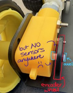
This week I made some key decisions regarding the physical robot implementation. Last week I wrestled with the dilemma that our original cheap Amazon robot chassis didn’t have proper encoder information. To determine next steps I weighed a lot of factors:

First, how necessary are encoders when we have an IMU? Quick search shows that encoder feedback data cannot be replaced by our 6DOF IMU units, and is very important to have long-run viable localization. Encoder data complemented by IMU data makes for the most accurate. Thus, I pursued encoder data further.

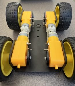
Secondly, how possible is it to jerry-rig optical sensors onto the bottom of the existing chassis? It’s cheap! 4-pack (one for each wheel) for $9 bucks on Amazon. But the footprint underneath the chassis is very small, and doesn’t allow for ample sensor room, additionally, there’s no where to mount them! I decided this solution is no easily replicable nor reliable, and this is important for the sake of SWARM since our goal is to have multiple identical robots at the end of the semester.

Lastly, we come to the option of buying a new chassis. What kit to get? Encoder motors and sufficient product specifications are necessary this time in order to make sure we don’t get misled by the advertising again. Between the two reliable suppliers that I found, HiWonder and Yahboom, they had high quality encoder motors, compatible motor drive boards, battery and battery charger kits, larger chassis footprint and mounting points, and much more security through documentation. The ultimate decision came down to drive train, where the Yahboom chassis had differential drive, vs. HiWonder’s Ackermann drive train. Ackermann drive train doesn’t enable turning in place, and we determined as a team that this was important for our 2D mapping use case, where a robot could find itself in a narrow corridor that it needs to get out from.

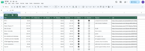
I updated the BOM with this new product, and returned a bunch of products that I bought for the old chassis to ECE Receiving.

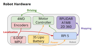
Additionally, with the Design Document due date being this week, I spent the rest of my time towards this. Contributing writing to assorted sections in the doc, and creating new, more comprehensive hardware design visuals to add.

Team Status Report for 10/18

This week we made key changes to the hardware of the robot, switching to a more expensive yet reliable Yahboom robot chassis kit. It is ordered and on track to arrive by the time we return from Fall break to enable swift assembly and integration with code. Otherwise the hardware design is the same, just with different parts that have guaranteed compatibility and much wider documentation.

Additionally, the team worked towards completion of the Design Doc, taking feedback from the Design Presentation into account and ironing out any questions that remain unanswered in each respective sub-domain and submitting a thorough and well documented final product.

A was written by Zhuoyi Zou, B was written by Rachel Lewis and C was written by _____.

Part A:

Our mapping system addresses the need of maintaining accurate spatial information in warehouses and storage facilities as their layouts change. Organizations in different regions may have different facility sizes, staffing levels, technical expertise, and access to computing infrastructure. We are therefore designing the system around reusable ROS 2 components and configurable robot interfaces, allowing the architecture to be adapted without requiring every deployment to recreate the entire software stack. The proposed ability to continue mapping during communication interruptions is particularly relevant to facilities with inconsistent wireless coverage. Processing sensor data locally also reduces dependence on a continuously available remote computing service.

This also requires considering who will operate and maintain the system. We should not require warehouse personnel to understand SLAM algorithms or ROS commands to interpret results. We plan to provide configured visualizations of maps, robot status, exploration progress, and detected environmental changes. Documentation and repeatable setup procedures will help maintenance personnel distinguish hardware faults, communication problems, and mapping failures. Although our initial prototype will be evaluated in a controlled environment, deployment elsewhere would require validation against local facility conditions and practices.

Part B:

Our robot swarm is designed with cultural factors in mind by making the system accessible to warehouse employees with different technical backgrounds and language abilities. The alert interface will be intentionally simple and non-technical, communicating key information about warehouse floor changes, such as the affected region and the severity of a blockage, without relying heavily on English text. This makes the system easier to use across workplaces with multilingual employees or managers who may not have experience with robotics or mapping technology. The robots themselves are also small, simple, and generally non-threatening in appearance and function. Rather than replacing existing warehouse jobs, they perform a supporting role by monitoring the floorplan and identifying changes that could interfere with normal operations. In this way, the system is intended to help existing employees and workflows operate at full capacity rather than substitute automation for human labor.

Part C: … with consideration of environmental factors. Environmental factors are concerned with the environment as it relates to living organisms and natural resources.
*How much energy does continuous mapping use? Can components be repaired instead of replacing the whole robot? Does better warehouse awareness reduce damaged products, wasted trips, or unnecessary equipment usage? Is the software able to operate on any type of robot?*

Team update for 10/03

The most significant risk of hardware delays has already occurred, due to the chassis we bought not coming with any encoders, and not easily being able to be fitted with encoders. The encoders are needed for running SLAM. Because we worked our design to be under budget, we have enough room to tolerate these setbacks and are currently researching alternative robot chassis.
We have not made any new changes to the system design yet, and adjusted the first-robot-assembly timeline to reflect the setbacks and be more realistic.

Zhuoyi’s update for 10/03

This week I worked on setting up SLAM-toolbox in a local environment. I set up a docker container running Ubuntu 24.04 and ROS2 kilted, which are the versions used by the distributed SLAM toolbox demo. I have successfully gotten SLAM toolbox to build and run in the dev environment, but am still currently debugging issues with getting the demo to work as well.
My progress is currently ahead of schedule. Despite the debugging hold, understanding ROS2 and its capabilities has drastically simplified the initial design of the software infrastructure, which originally we dedicated an extra week to.
Next week, I hope to get the SLAM toolbox demo working properly, and develop an interface to implement our own additions to the library.

Rachel’s Status Report for 10/3

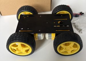
Ran into some obstacles while assembling the newly arrived parts and trying to test the chassis motors:

  • the raspberry pis did not come with microSD cards. Thus we can’t yet run any OS on them nor use them to test the robot chassis
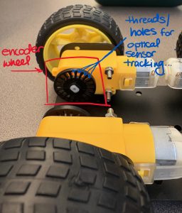
  • the chassis kit contains encoder wheels, but no sensors that would return any useful data from the wheels… Thus, even if we could drive the car, we don’t have motor feedback which can be problematic for accurate driving.

Considering these obstacles, this week I accomplished:

  • assembling the first chassis

  • ordering microSD cards + adding to the team BOM
  • change team Gantt chart to reflect new schedule due to set backs, specifically my task timeline
  • created a working doc for my hardware-assembly specific tasks to make it easier to map next-steps in order to prevent set backs from unforeseen obstacles and keep track of my progress

To accomplish next week:

  • comprehensive design plan that considers more thoroughly the end-to-end robot in order to prevent similar set backs in the next attempt at reassembly
  • evaluate and order new chassis with actual encoder motors!


Kevin’s Status Report for 09/26

This week I focused on the SLAM and mapping portion of SWARM, and I also prepared for the design review presentation. I worked on improving the software architecture for the distributed mapping system, and I also investigated how SLAM Toolbox fits into the ROS2-based architecture. SLAM Toolbox is a better fit for this project compared to DOOR-SLAM because it supports LiDAR and ROS2, and it also provides functionality for decentralized multi-robot mapping.

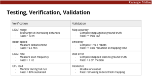
I also worked on defining how we’ll quantitatively test and validate the system. The design requirements are mapped to specific tests, like LiDAR range, scan frequency, robot speed, wall-position error, etc.

My progress is currently on schedule, and the main dependency is receiving and assembling the physical robot hardware. Next week, I plan on working with the team to assemble the physical robot and integrate the SLAM software to begin initial mapping tests.

Zhuoyi’s Status report for 09/26

This week, I worked more on the robot communication infrastructure. Testing on the Ubuntu Linux Docker environment, I have infrastructure code performing all of the standard distributed communication patterns over ROS2. I prepared a ROS 2 Python demonstration package with three peer nodes. It exercises direct messages, broadcast, scatter, gather, reduce, allgather, allreduce, and a barrier. The package includes the node code, a launch file, and instructions for running the peers on separate computers.

I also outlined the software architecture for the design review: each Raspberry Pi runs its own sensor input, odometry, SLAM, and robot control software. The robots exchange mapping data over ROS 2, while RViz2 observes the results.

The progress is on schedule, next week I will be working with the team to integrate the infrastructure and Kevin’s SLAM work onto actual robot hardware for testing. This work will begin once the robot components arrive.

Team Status Report 9/26

This week, on the robot-hardware side of things, the team fleshed out a wiring plan for the bot and ordered all associated components to be assembled next week.

Again, the most significant risk is a hardware defect or delay, which would push back all of our integration and on-robot development work. Our plan is still to leave enough budget and time in the event of any hardware issues.

We changed the design to use SLAM-toolbox instead of DOOR-SLAM. This was because DOOR-SLAM uses camera input, which is not compatible with our LiDAR-only design. Additionally, SLAM-toolbox has been designed with distributed fault tolerance in mind, is natively ROS2 + LiDAR, and has a built-in simulator for tests when hardware is not available.

A was written by Zhuoyi Zou, B was written by Rachel Lewis and C was written by Kevin Huang.

Part A:

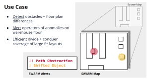
SWARM is intended to help warehouse staff identify blocked aisles and shifted obstacles by comparing the robots’ updated map with the expected layout. An alert would direct staff to a specific location so they can assess and clear a hazard, or identify security issues preemptively, which would help keep routes accessible for safe worker and goods movement. We will test obstacle detection and alert accuracy before claiming that the system reliably identifies hazards.

The robots could themselves create a collision hazard when operating near people. Our safety design will limit robot speed during testing, stop motion when an obstacle is detected or required sensor data becomes unavailable, and provide a human-operated way to cut motor power. We will verify stopping behavior and sensor-failure responses during our development and testing.

Part B: For our obstacle-alerting system that is built on top of the 2D mapping data we receive from our robot SWARM, we are imagining a very clean and simple UI that is universal in understanding across diverse users. This is our main social factor consideration, to ensure that our final product is actually usable in the real world, to folks without an engineering or software or robotics background.
Ultimately, the goal of our technology is to promote warehouse operations to work as smoothly as possible, and this by nature doesn’t touch many of the realms of social considerations, like politics or culture. That being said, a connection could be made between providing the most accurate up-to-date data and improving the collaboration, culture, and social atmosphere of the warehouse working environment. Bringing real-time, reliable notifications of obstructions and potential discrepancies on the warehouse floor could surpass the office politics of word-of-mouth telephone, seeking approval/intervention from different departments, or worker-by-worker opinions/arguments about what-should-be-where-and-why. With the source-map underlying our technology, and the live mapping on top, obstacle detection is simple, accurate, and can be alerted to the folks in charge right away.

Part C:

For economic factors, we focused on keeping SWARM relatively low-cost and scalable by using cheap, commercially available components such as Raspberry PIs, LiDAR sensors, and publicly available robot chassis (instead of using specialized industrial hardware). This makes it easier to add additional robots to the system without requiring expensive hardware or centralized compute infrastructure. Since each robot is designed as a standalone unit that can do mapping and computation by itself, the system can continue operating if an individual robot fails, which makes failures much more economical than if there was a single expensive central point of failure.

In a warehouse, the economic benefit comes from reducing the amount of manual effort and time required to inspect and update warehouse layouts, and from identifying misplaced inventory or blocked paths more quickly. Using multiple robots helps reduce mapping time, which could streamline and reduce downtimes in warehouse operations. On the other hand, adding robots increases the hardware, maintenance, and replacement costs, so adding more robots only makes sense if they provide a significant improvement in mapping time and coverage.

We also considered repair and replacement costs when we selected components. Our design uses modular and replaceable parts, and we leave room in the project budget for duplicate robots and replacement components, which further reduces the impact of individual hardware failures.

Rachel’s Status Report for 9/26

This past week I finalized the hardware selection for our first prototype bot in order to have parts ordered on Thursday, so they arrive next week for full assembly.

I also contributed key slides and visuals (made in Canva and Slides) to our team Design Presentation deck in order to assist in an easy-to-understand delivery next week.

Before this week there was a black-box in my mind where the power and wiring of the robot lived, that I had to actually make concrete. I’ve never built an entire robot from scratch, so I was very careful in my approach. I started with the components we knew we needed to connect: Robot Chassis Motors, RPi 5, Lidar, IMU. From here I had much back-and-forth with ChatGPT to research and learn about the required components to connect and power each of these safely.

With some time, I established that power from our battery needed to be split into two separate streams: 5V 5A, as per the RPi 5 documentation, and 6V 10A, estimated (with plenty of buffer) based on the limited specs on the robot chassis motors. These two desired voltages informed my part search, along with economic considerations, because as a team we want to maintain room in the budget for a duplicate bot, PLUS extra wiggle room for part replacements/changes/fixes etc.

I had ChatGPT create a block diagram of how the new parts will be connected in between the core components (Robot Chassis Motors, RPi 5, Lidar, IMU), the final iteration shown below.
SWARM bot wiring diagram

After research and part finalization, I updated the team BOM to do auto total-price calculations in order to save time in the future, and logged the new parts to order.

I am currently on track with the team Gantt Chart. Assuming all parts arrive next week (which they should considering it was all <2 day Amazon Prime shipping), I can stay on pace. Next weeks’ tasks are transitioning from planning/digital work to physical assembly of the chassis, drivetrain, wiring connections, and mounting of sensors. The most immediate next step is going to be creating a more detailed wiring diagram for pin connections between the Rpi, Lidar, and Motor Controller specifically based on documentation pin-outs.

Some questions left unanswered are:
Chassis encoder output voltage (not documented anywhere) is 5V or 3.3V? This determines if it is directly compatible with the Rpi 3.3V GPIO pins or not.
Motor stall and startup current quantity (not documented)? I built in buffer for these current spikes into the battery, buck converter and wire ratings, but it’s important to quantify them to make sure we won’t have any issues down the line.