Team Status Report for 12/9/23

Unfortunately we ended up making the decision to not implement diodes in our project. Devan was having too much difficulty with the implementation. The positive side to this is that our circuit classification accuracies have gone up, because previously there were some cases where switches would be classified as diodes. The component classification accuracy has stayed the same at around 83%, and the circuit classification accuracy is around 86%. Because we removed diodes, we have to redraw test images that were used that contained diodes. We plan on continuing testing a lot tomorrow and next week, just to get plenty of data to use in our report.


Computer vision unit testing:

  • Individual component classification testing
    • Tested different image preprocessing algorithms and parameters
    • Tested how classification performed with various implementations
      • With special casing on wires
        • Determined that this was highly effective in classifying wires, which allows us to remove wires from the dataset so we don’t even have false positives of wires
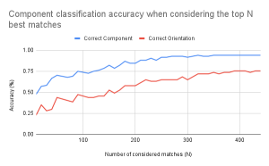
      • With varying numbers of matches considered (ex: only considering the top 20 matches of features between the component image and a dataset image)
        • Determined that considering all the matches and not leaving any out had the highest classification accuracy
      • With different feature matching algorithms
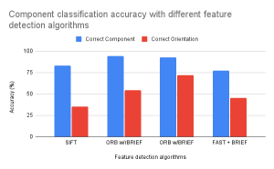
        • Determined ORB feature vectors + BRIEF descriptors was the best combination
      • With circle detection to separate voltage+current sources and lightbulbs from other components
        • Determined that the circle detection was beneficial and worked well in identifying voltage+current sources and lightbulbs
        • Interestingly resistors would also get detected to have a circle, but this ended up being fine because in the feature matching there would be a clear difference between the resistors and circular components
      • If a component’s best matching score doesn’t reach some sort of satisfactory threshold, rerun the component matching with all component types in consideration (redo without circle detection)
        • Determined that a consistent threshold could not be determined and that the circle detection was more accurate
    • Tested with various sizes of the dataset
      • Notably as long as there is at least one image of a component in each of its possible orientations, the classification accuracy was similar to when having multiple images.
      • Need to test more with this
  • Node detection testing
    • Tested different image preprocessing algorithms and parameters
    • Tested images with different lightings and shadows
    • Determined that even with improper lighting, the node detection works well as long as the nodes are drawn large enough and are properly filled in
  • Full circuit classification testing
    • Tested complete computer vision code with circuit images of various number of components (4 to 10)
      • Determined that all incorrectly classified circuits were because of poor component classification, not because of failure of node detection

Circuit Simulator Testing

  • Generate netlist with maximum of 8 components
  • Run netlist through existing simulator tool
    • CircuitLab
  • Compare results of simulation 
    • Voltage at every node
    • Current through each component 
  • Tested 25 circuits
    • Voltage Sources, current sources, resistors, light bulbs
  • Current and voltage were correct on every circuit
  • 100% simulator accuracy given a netlist

Usability Testing

  • Surveyed 7 individuals ages 12-14
  • Gave them circuits to draw
  • Answered questions on a scale of 1-10
  • “How easy was it to upload your circuits?”
    • Average score 10/10
  • “Was it clear how to input values?”
    • Average score 6/10
    • Found confusing which component they were inputting values for
  • ““How useful were the tips on the home screen when drawing your circuit?”
    • Average score 7/10
    • Found example drawing of circuit most helpful
  •  “Were the headers of the page useful when asked to do complete some task”
    • Average score 9/10
  • “Do you think adding more tips and headers would make it more clear”
    • Average score 7/10
  •  “How clear were the schematics of all the circuits displayed?”
    • Average score 9/10
  •  “How easy was it to recognize what you needed to redraw with your circuit if it wasn’t an option?” 
    • Average score 7/10
  • Average score of survey 7.85
  • Working on implementing a more clear way to input values for components 

Devan Grover’s Status Report for 12/09/23

This week I finished up some polishing touches on the circuit simulator and finalized some of the integration of our project. Stephen changed his computer vision algorithms to use functions that are not available in the default opencv framework. This means we have to build the framework using additional modules. I ran into some issues doing this because I have an Apple Silicon Macbook, but we hope to resolve this issue by using an Intel Mac.


I also polished up some of the integration code between the simulator and the rest of the app. Previously, the app would crash on my section if there were errors in the program. I have mitigated this issue and the app no longer crashes when the simulator errors out.

Jaden D’Abreo Status Report 12/09/2023

This week I finished the iOS application, conducted usability testing, and tested the full pipeline of the code. I was able to finish the iOS application early and the week which allowed me to schedule interviews throughout the week to conduct usability testing. The surveys went well, however there is a clear problem with the way we ask users to input values for the circuit. The overwhelming response was that they found it confusing which component that were inputting a value for. Therefore, I plan to try and incorporate adding a number below or next to the components that correspond to the label in the input field. Hopefully by doing so this would cause less confusion. I have asked a couple individuals from the test group to meet again early next week and have them answer the question regarding inputting values once more. The usability results were slightly lower than we wanted, however making the changes to the inputting page should get us to our goal comfortably. The pipeline is fully functional, there are some minor changes that need to be implemented. When the user uploads a bad picture, instead of not doing anything I plan to add some text saying the picture was not readable. Apart from this there is not much else that needs to be done. I plan on adding these minor changes tomorrow and begin working on the design report. 

Stephen Dai’s Status Report For 12/9/23

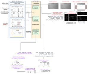
Unfortunately this week I did not get to spend as much time on testing as I wanted. Because we decided to not implement diodes, I had to get rid of their classification from the code and dataset. I also ended up spending more time on the poster than we should have, but in my defense it was to make this awesome diagram:

Tomorrow I am going to do a lot more testing. Unfortunately some circuit test images will need to be redrawn because they contain diodes. Interestingly I noticed from the component classification testing that current source orientations seem to be working well, but not so much voltage sources. Hopefully I will be able to identify what could be the difference and what a solution for it is. Because there are no diodes now switches aren’t getting misidentified as diodes, but there does seem to be a rare case where a resistor/switch gets identified as the other. I will look into this as well and see if I can identify another solution.

Other than this our CV is in a decent state for the demo. As long as my group members have properly finished the integration and their parts, our demo should be good to go.

Team Status Report for 12/2/23

Stephen managed to get the individual component classification accuracy up to around ~85% in testing, and is still in the process of measuring the full circuit accuracy. The size of the dataset has increased to encompass 56 component images, but in terms of file size it is actually still 3 MB, which is what we predicted two weeks ago. In addition to this, because Stephen switched to using BRIEF descriptors, which are only available with opencv-contrib extra modules, this is an added step for the build process of the integration. This week we were able to completely finish integrating the entire project on one codebase. The CV and the phone app are correctly linked to display the circuit that the CV algorithm recommends and the circuit simulator is able to run with the inputs the user provided. All that is left to be done is to parse the output of the circuit simulator and display it on a final page, however this will be less than a day’s work as we have already parsed the output of the CV code which was far more challenging. In addition to this, the display of the circuit has a couple bugs that need to be worked on, but this is also expected to take around a day. Jaden is planning on finishing both these parts by Tuesday. 

Now that most of the integration is finished, Devan is finishing up working on the model for the diode. Once these parts are finished, the project will be completed.

Jaden D’Abreo Status Report 12/02/2023

This week I made final touches to the phone application and started integrating all the subsystems together. Integrating was a bit challenging, however it was completed! Dev and I were able to integrate each subsystem together and now the project can be completely run within one codebase. As this was our first time working with Swift, the process took a lot of time to debug. Dev and I were first able to complete integrating the phone application and the circuit simulator, therefore I was able to model his header and bridge file to model my integration with the computer vision. Thus, once completing the first integration, the second integration was a bit more straightforward, but still challenging. There were a lot of additional things needed to be added to the codebase to make the CV and the phone application work together. Bridging these two systems together required saving the state of file paths, adding extra parameters, and modifying both existing codebases, the phone application and the CV, to function properly. However, there is still one bug that needs to be fixed. The circuit does not display as it did with the hard coded coordinates due to a slight flaw in logic. However, this is not a very pressing bug and should be resolved within a day’s work. The correct components were placed on the screen, just not in the correct position, and I have located the flaw in the code. In addition, I have to display the contents from the circuit simulator, however this will also be even less work than the other fixing the bug. I am slightly behind on my work, I expected to be completely integrated and finished with the phone application by this week, however with the final presentation tomorrow, as I will be presenting, I will turn my focus tomorrow to that. Even though I am behind on my work, I believe the status of the project is in a great place and the entire system will be completed early this coming week!

Devan Grover’s Status Report for 12/2/23

This week I worked a lot on integration of the parts of our app. I first had to get openCV to build on our iOS platform. I ran into many issues because Jaden and my computers have Apple Silicon, which makes us unable to test our code on the iOS simulators on our systems. We initially remedied this by working in WEH5201, but I set the project up so that we can now build directly on our phones from our own machines.

I had to create an objective-c++ file to bridge the code between the frontend and backends of our application. This meant learning the syntax and nuances of objective-c++, which is very different to other languages I have used in the past. I had to create new data structures that were compatible with objective-c++ and Swift so that I could pass data between the two languages. This meant I also had to do more work in the simulator to parse this new data structure into a readable structure for the simulator. I also helped Jaden integrate the CV with the app in a similar fashion with an objective-c++ file.

Now that we have a working application, I will resume my focus on the diode model in the circuit simulator. I am a bit behind schedule on the diode, but believe I will be able to complete it by the end of next week. I am satisfied with this past week’s progress because we have integrated our application’s parts together.

Stephen Dai’s Status Report for 12/2/23

This week I continued working on the individual component classification testing and the full circuit classification testing. The dataset is now complete and finalized representing 54 component subimages. I also factored in each orientation (left, right, down, up-facing) of voltage sources, current sources, and diodes into the code. To do this I had to not use the rBRIEF (rotated BRIEF) descriptors that ORB uses, but just the standard ORB descriptors. Unfortunately this required me to use the opencv-contrib extra modules, which required me to build the opencv library from source with the extra modules included, which took like 10-15 hours. In the meantime I used my python code for the testing. The good news is that the new component classification measurements are now ~94% on correct component classification, and ~79% for the correct orientation, which is now a raw component classification score of ~85%. It is not exactly the >=90% we originally outlined, but I am pretty happy about it. See the below graphs for some comparisons I made.

I also started doing the circuit classification testing. As of now I have only done 12 tests and 9 of them were correctly classified. Oddly enough what was the root of the problem in the three tests I failed was that switches could not be classified properly, which shocked me because in the individual component classification testing they were the most accurate by far. I am going to continue looking into how to solve it. It doesn’t seem like an issue with my individual classification testing because when I added the switch subimages generated from the circuit classification testing, they also failed, so I guess it just turns out that the ones used in the individual testing set were similar to those in the dataset.

For next week I am going to continue the full circuit testing and make some deliverables (graphs, tables) to show the result of the testing. I will also look into the switch thing and further classification improvements as I see fit. I am decently satisfied with the state of the computer vision and believe it is decently ready for final demonstration.