Team Status Report for 12/9/23

Unfortunately we ended up making the decision to not implement diodes in our project. Devan was having too much difficulty with the implementation. The positive side to this is that our circuit classification accuracies have gone up, because previously there were some cases where switches would be classified as diodes. The component classification accuracy has stayed the same at around 83%, and the circuit classification accuracy is around 86%. Because we removed diodes, we have to redraw test images that were used that contained diodes. We plan on continuing testing a lot tomorrow and next week, just to get plenty of data to use in our report.


Computer vision unit testing:

  • Individual component classification testing
    • Tested different image preprocessing algorithms and parameters
    • Tested how classification performed with various implementations
      • With special casing on wires
        • Determined that this was highly effective in classifying wires, which allows us to remove wires from the dataset so we don’t even have false positives of wires
      • With varying numbers of matches considered (ex: only considering the top 20 matches of features between the component image and a dataset image)
        • Determined that considering all the matches and not leaving any out had the highest classification accuracy
      • With different feature matching algorithms
        • Determined ORB feature vectors + BRIEF descriptors was the best combination
      • With circle detection to separate voltage+current sources and lightbulbs from other components
        • Determined that the circle detection was beneficial and worked well in identifying voltage+current sources and lightbulbs
        • Interestingly resistors would also get detected to have a circle, but this ended up being fine because in the feature matching there would be a clear difference between the resistors and circular components
      • If a component’s best matching score doesn’t reach some sort of satisfactory threshold, rerun the component matching with all component types in consideration (redo without circle detection)
        • Determined that a consistent threshold could not be determined and that the circle detection was more accurate
    • Tested with various sizes of the dataset
      • Notably as long as there is at least one image of a component in each of its possible orientations, the classification accuracy was similar to when having multiple images.
      • Need to test more with this
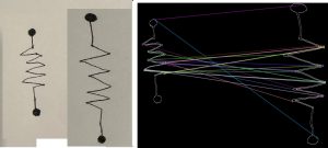
  • Node detection testing
    • Tested different image preprocessing algorithms and parameters
    • Tested images with different lightings and shadows
    • Determined that even with improper lighting, the node detection works well as long as the nodes are drawn large enough and are properly filled in
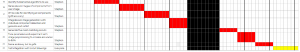
  • Full circuit classification testing
    • Tested complete computer vision code with circuit images of various number of components (4 to 10)
      • Determined that all incorrectly classified circuits were because of poor component classification, not because of failure of node detection

Circuit Simulator Testing

  • Generate netlist with maximum of 8 components
  • Run netlist through existing simulator tool
    • CircuitLab
  • Compare results of simulation 
    • Voltage at every node
    • Current through each component 
  • Tested 25 circuits
    • Voltage Sources, current sources, resistors, light bulbs
  • Current and voltage were correct on every circuit
  • 100% simulator accuracy given a netlist

Usability Testing

  • Surveyed 7 individuals ages 12-14
  • Gave them circuits to draw
  • Answered questions on a scale of 1-10
  • “How easy was it to upload your circuits?”
    • Average score 10/10
  • “Was it clear how to input values?”
    • Average score 6/10
    • Found confusing which component they were inputting values for
  • ““How useful were the tips on the home screen when drawing your circuit?”
    • Average score 7/10
    • Found example drawing of circuit most helpful
  •  “Were the headers of the page useful when asked to do complete some task”
    • Average score 9/10
  • “Do you think adding more tips and headers would make it more clear”
    • Average score 7/10
  •  “How clear were the schematics of all the circuits displayed?”
    • Average score 9/10
  •  “How easy was it to recognize what you needed to redraw with your circuit if it wasn’t an option?” 
    • Average score 7/10
  • Average score of survey 7.85
  • Working on implementing a more clear way to input values for components 

Team Status Report for 12/2/23

Stephen managed to get the individual component classification accuracy up to around ~85% in testing, and is still in the process of measuring the full circuit accuracy. The size of the dataset has increased to encompass 56 component images, but in terms of file size it is actually still 3 MB, which is what we predicted two weeks ago. In addition to this, because Stephen switched to using BRIEF descriptors, which are only available with opencv-contrib extra modules, this is an added step for the build process of the integration. This week we were able to completely finish integrating the entire project on one codebase. The CV and the phone app are correctly linked to display the circuit that the CV algorithm recommends and the circuit simulator is able to run with the inputs the user provided. All that is left to be done is to parse the output of the circuit simulator and display it on a final page, however this will be less than a day’s work as we have already parsed the output of the CV code which was far more challenging. In addition to this, the display of the circuit has a couple bugs that need to be worked on, but this is also expected to take around a day. Jaden is planning on finishing both these parts by Tuesday. 

Now that most of the integration is finished, Devan is finishing up working on the model for the diode. Once these parts are finished, the project will be completed.

Team Status Report for 11/18

One change that has an associated cost is the memory usage of the dataset file. Stephen created a YML file with feature vectors representing 27 component images that had a size of 1.4 MB. Our ideal dataset size would comprise 54 component images, which would correspond to a YML file size of ~3 MB. This is bigger than our previously anticipated 500 KB size for 50 component images, but because our maximum application size is set as 100 MB, we don’t expect this 2.5 MB difference to be a problem. In addition, there were some changes regarding how the user will input the component values. When showing progress there were concerns of the UI and it being tailored to a younger audience. Now rather than the user clicking on components to input values, they are presented with text of each component name to click on to input values. We expect this will be more user friendly and will cause less confusion.

We also worked a bit on integrating the computer vision and circuit simulator components of our project. Our circuit simulator is now directly able to simulate a circuit from an image generated by the computer vision algorithm. We are still unable to get the computer vision library to build for XCode though, which may mean we will have to use the Intel Mac lab.

Overall we are more behind schedule than we would like, but hope to make this up over next week’s break. Our goal is to have the full integration complete by the time we come back from break, which gives us time to work on final documentation during the first week back. 

We have all developed lots of skills that we did not previously have by working on our application. Stephen had never used computer vision before, Jaden had never coded an iOS app before, and Devan had limited c++ experience. By working on this project, we were able to develop our skills and become better engineers. From a logistical standpoint, we have learned to work well together by giving each other status updates often to mark our progress and make sure we are relatively on track. This also allows us to pass ideas between each other even though our work is very compartmentalized. Planning the gantt chart also helped a lot because we are able to manage our time better and not spend too much time thinking about what to do next after completing a task. 

Team Status Report for 11/11/23

Stephen made several large changes to the computer vision subsystem in an effort to improve accuracy of classifications so that we can hit our accuracy requirements. Because of this, he did not get to performing benchmark tests to quantify how accurate the system is as of now. The goal for the end of this week was to get 80% accuracy and 90% next  week. As long as by the end of next week Stephen can hit close to the 90% mark, he will remain on schedule. Otherwise, we will have to use some slack until this mark is hit.

Jaden worked on the application’s UI, specifically the value input for components. He was able to get the feature to work in a way where you can tap on each individual component on the circuit and enter in a value. He still needs to figure out how to display these values onto the screen though. Devan worked mostly on trying to integrate diodes into his circuit simulator. This proved to be very challenging because he has to incrementally solve a system of equations in a loop until his solution converges. He is a little behind, but will make this up over Thanksgiving.

Starting next week we’re going to gradually start working on the integration of our subsystems. This means creating bridge files for the C++ classes that Stephen and Devan have created, as well as some other minor details like what was mentioned in last week’s report.We will also start doing unit and integration testing in order to benchmark requirements and make further refinements.


Team Status Report for 11/04/23

We are on schedule with our progress. This week we finished developing our subsystems so that we are ready for the demo next week. Stephen finished converting the Python proof of concept to C++ code, and has developed a functional example of the computer vision system that he will show during the presentation. Jaden was able to finish debugging the phone application and is now able to display the circuit components with coordinates with a sliding page model. Devan was able to correctly simulate circuits that contain voltage sources, current sources, and resistors. Therefore, we now have each individual subsystem working at a basic level to show for the demo next week.

For the coming weeks we plan to start integrating the subsystems. We expect integrating the phone application and the computer vision code to take time and involve debugging. Therefore, before making further advancements on each subsystem our priority is to integrate and test the subsystems as one system. It should not be too tough to integrate the simulator with the application because the simulator has been developed within the build environment for the application. This means we already know the code to simulate circuits can be built and run on an iOS device like we intended. We are currently on track with the schedule we have planned.

Team Status Report for 10/28/23

There have been no major changes this week. The system and schedule are still the same, however there were a couple problems with the phone application this week. There is a bug creating the pages to display the circuit and was not resolved due to the ethics assignment taking up a lot of time. The frontend components were created, however they are not displaying on the sliding page correctly given coordinates. This is not a significant risk as this bug should be resolved within a day, however if it continues to persist into next week we plan to implement a different way to display the images instead of a sliding page. This would most likely be individual pages rather than just one. Even with this bug no changes are made to the schedule because the phone application should be able to display full circuits by next week given coordinates. Everything else is still on track.

We also got some bugs when trying to port the python code over to C++ this week. Thus far, all of the computer vision algorithms have been written in Python. Since our application is an iOS application, we will need to switch it to C++ code to build for iOS. We also made some progress on the netlist parsing for the circuit simulator. We now have an algorithm to parse through the netlist and are trying to generate the matrices using the Eigen library we installed last week.

Team Status Report for 10/21/23

One major change that we thought of over fall break is what circuit data structure we send to the frontend of the application from the computer vision output. Previously we have been set on a netlist: the computer vision sends a netlist to the frontend, and the input to the circuit simulator is also a netlist. What we have realized while constructing the netlist from the computer vision algorithm is that there is a discrepancy between the circuit that the user drew and the orientation of the circuit that the netlist represents. A properly constructed netlist (which is easy to do) will guarantee that the right components are connected at the appropriate nodes and that the relative positioning of each component to one another is correct. What a correct netlist does not give us is the same orientation of the circuit as what the user draws. For example, say that a user draws a circuit where the components starting from the left side and going in a clockwise direction are voltage source -> resistor -> wire -> wire (back to voltage source). The generated netlist will guarantee this ordering, but when drawn the circuit could look like (also from the left side, clockwise) wire->wire->voltage source->resistor (back to wire). We may end up accidentally throwing the user off by showing them what is technically the same circuit as the one they drew but oriented differently, which may lead to correct circuit classifications not being deemed correct by the user. Our solution to this also simplifies some work; the computer vision algorithm naturally produces a list of edges where each is denoted by the coordinates of a pair of connecting nodes and the component that is connecting the nodes. By giving the frontend the coordinates of the nodes, they can construct the relative orientation of the circuit that the user expects. We made progress with the circuit simulator by installing the required libraries to the development environment and creating the required matrices. 

There have been no changes in the schedule. We are on track with our work and plan to meet all of our deadlines accordingly. Next steps include testing the iOS application to make sure it will integrate with the computer vision algorithm correctly. This means feeding coordinates into the application and making sure the circuits displayed are correct. 

Team Status Report for 10/7/23

The only major changes made to the design were the addition of preprocessing algorithms to the computer vision. We knew that we were going to have these, but we weren’t sure exactly what algorithms we were going to use. Upon receiving the user’s image, we grayscale it, then do some simple thresholding to get rid of the effects of different lightings and shadows and the grain of the paper. Then, we do some aggressive median blurring that will eliminate all drawing marks except for the dark, filled in circles representing nodes. This has been the major change and success that has allowed our use of Hough circles to work (see Stephen’s report for more information). 

This was the first week since we changed to an iOS application from a web application. A lot of the early stages of the week was researching Swift and looking through examples to develop some of the UI for the app. The front page of the app has been completed and the page that uploads the photo needs just a little more time to be completely finished. The next step will be to feed the picture of the uploading hand-drawn image into the computer vision algorithm. 

The schedule is the same except for Stephen’s schedule rework (see below). The circuit simulator is running a bit behind due to Devan getting sick, but he will work over fall break to make up for the lost time. Jaden will also be working on the phone application throughout fall break.

Two engineering principles that we used to develop our design are linear algebra and image processing. For our circuit analysis tool, we need to run nodal analysis on nearly every single node in the circuit. This involves setting up a system of equations that models the voltages and currents going into and out of each node. By calculating equations for each node, we then will solve the matrix system of equations that represents the circuit. We also need to process the images that users input in order to make them easier for our computer vision algorithm to recognize. The images go through a grayscale filter, a binary threshold filter, then a blur in order for our algorithm to detect the nodes at the end of each component.

Team Status Report for 9/30/23

One of the most significant risks in our project lies within the accuracy of our computer vision algorithm. We plan to combat this by using a suggestion box after analyzing a circuit – this box will display the five circuits that our algorithm has the highest confidence in. From these circuits, the user can choose which circuit is the one that they drew. By doing this, we are able to achieve higher levels of accuracy without needing to perfectly detect every component. We also are moving the labeling of each component value to the application instead of in the drawing. Rather than having users write the value associated with a component right next to it, we will have them enter in the relevant information once the circuit has been loaded into the applications. This way our computer vision algorithm will not have a hard time trying to figure out which value is associated with each component.

Changes were made in regards to our initial idea of creating a web application. After discussion, our group came to a conclusion that using a mobile application would make more sense given our specified use case of accessibility for middle schoolers. Due to this, all the work done on the web application will be discarded and next week Jaden will be focusing on learning and developing the mobile application instead. As around a week of work has been voided, more hours must be put in to make up the time that was lost over this past week.

We have also been spending lots of time on creating our design presentation – we made many changes since our proposal presentation that had to be added to the design presentation. While creating the presentation, we did lots of research on other computer vision algorithms that were used in similar applications to figure out how to justify our accuracy expectations. Between the team over 20 research papers were looked into in regards to this issue. Papers included sentence recognition, electronic component recognition, and other computer vision models. We ultimately decided that for computer vision we will utilize the Hough circle algorithm for image segmentation, ORB transform for feature detection, and a Brute Force matcher for feature matching.

We ended up making many changes to our project in the past couple of weeks that we believe will help mitigate risks that will occur with our computer vision algorithm and with having a complex backend. Even though we wasted a week on the web application, since we do not have to setup a complex backend we are still on track with our schedule and are making good progress with our project.

Team Status Report for 9/23/23

One of the features that could jeopardize the progress of our project is our CV algorithm. Majority of our group’s time spent this week was researching and testing different types of image, feature, and edge detection algorithms on hand drawn circuit components. While we have made progress honing in on the type of algorithm we want to use, there is still a lot of uncertainty that needs to be solved. Since we have just been researching this week no changes have been made to our initial plan. The block diagram needs to be modified slightly. What we did not account for was our CV algorithm needing to interact with the database in order to pull training and validation data. This isn’t going to incur any extra costs or difficult refactoring because we knew we would be using a database anyways. Besides this, there are no changes to what we discussed in our proposal presentation.

 Next week we would like to start testing algorithms that can separate electrical components given a whole circuit and keep experimenting with individual component detection. When researching this past week, we realized that trying to extract sub-images of the individual components from a picture of the entire circuit is harder than we thought, as per Devan’s work this week. We will likely require dots/circles at the end of each terminal of a component to mark each individual component. At this moment we have not made any scheduling changes. Prior to making the schedule, we understood that since none of us have any CV experience that deciding on an algorithm would be paramount to this project’s success and so we have dedicated time to research. Given our current progression and the deadlines that are approaching, we are confident that we can stay on track to our initial plan and finish everything we planned to finish for the next week. 

We considered both public health + safety and economic factors as we developed our proposal. Firstly, our project reduces the safety risk that electricity poses to children trying to construct circuits. This is very important because parents can have peace of mind that their children will not be hurting themselves when learning about electricity. We also are aiming to reduce the cost that students and their families will incur by studying electricity and circuits. People will no longer have to pay 75+ dollars for a power supply, breadboard, wires, and resistors – instead they can just use our product for free.

Here is what comparing two drawn resistors looks like to the computer: