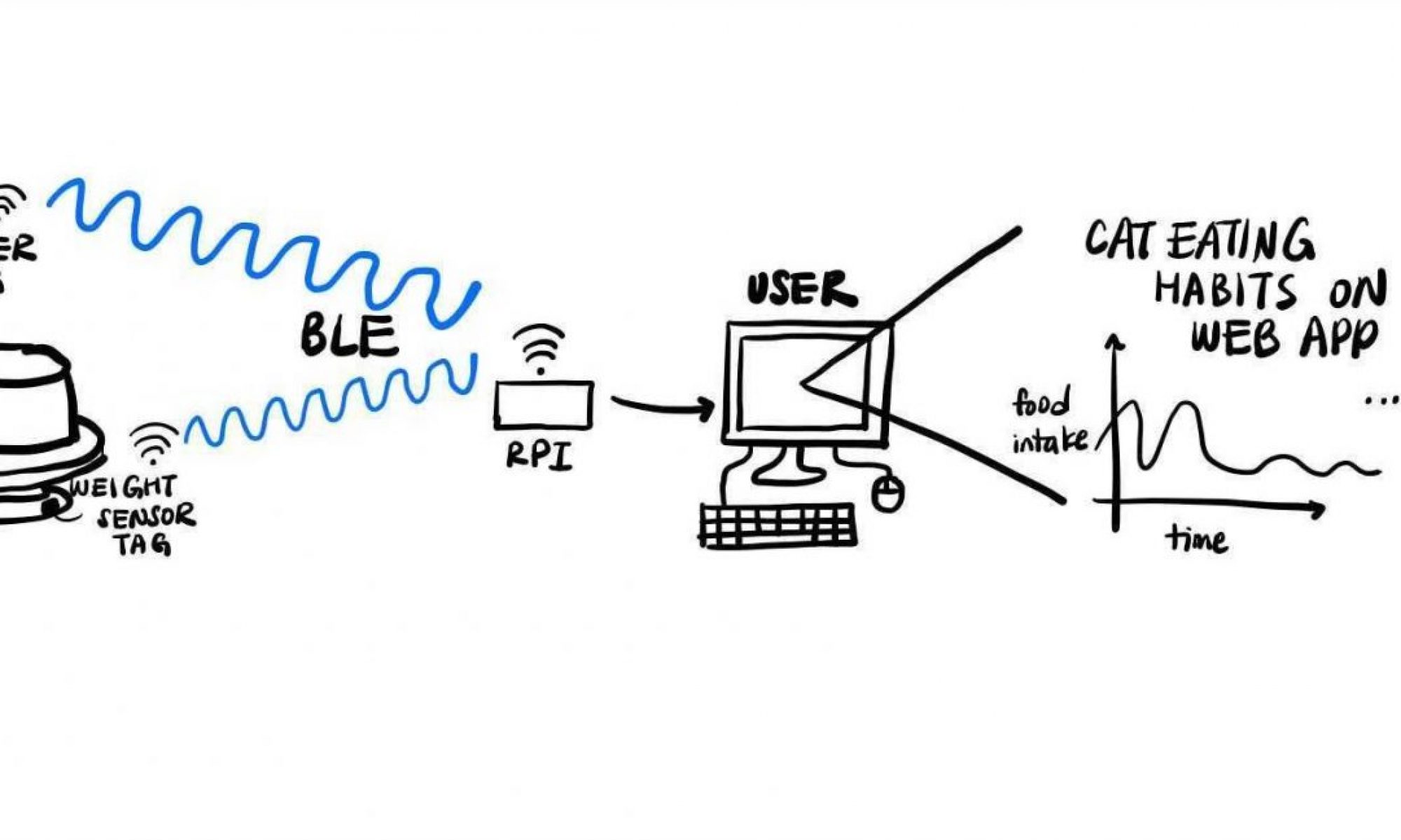
This week I mainly worked on getting the demo fully ready and then continuing to build and polish from there. I was responsible for the hardware portion of our demo, which was a bluetooth enabled weight sensor. The device featured a load cell housed in my custom enclosure connected to an HX711 breakout board, which in turn communicated with our DA14531 USB Dev Board to read out weight values. Our demo was essentially a not-yet-fully-integrated version of our weight sensor tag.
The basic functionality of the demo involved a custom driver for the HX711, which would begin pulsing a system timer upon bluetooth connection being established. The driver waits for the “value ready” signal from the HX711 and then pulses out 25 rising clock edges. In turn the HX711’s shift register shifts out a 24 bit weight value which is then interpreted by the dev board. If the value is above a preset threshold, the dev board lights an indicator led. I primarily included the indication led to demonstrate threshold values because the device’s UART does not seem to be functional. Because it cannot therefore display values it receives in real time, I used the led as an alternative.
On top of firmware development, this week also saw big strides on the hardware front. The PCB’s are almost fully finished, and I have now designed, etched, populated, and successfully tested versions 1 and 2 of our custom load cell breakout.

The breakout board has several benefits over off-the-shelf breakouts, primarily in terms of flexibility. I included a number of custom designed solder bridge pads that can be connected or disconnected to select between a number of features the HX711 chip offers. The most important of these is the RATE selection line – grounding it versus tying it to VCC selects between 10 and 80 Hz data rate. Leaving both rates as an option allows for testing which pulls less power and thus gives us more room for customization along the lines of power savings vs. speed as we polish the sensor tag design.


I also worked on getting the PCB’s finished and ordered. I finalized the parts list and finally had the order placed. Unfortunately, I encountered a silly mistake late in the design process – we needed one more GPIO than the DA14531 chip had available! Essentially, the problem came from a late decision to have the RFID sensor tag run an accelerometer which would sense vibrations caused by a cat accessing the food bowl. Upon detection, the sensor tag would turn on the RFID reader to scan the cat’s ID chip. This design decision centered on the key point that the accelerometer would be orders of magnitude less power hungry than the RFID reader (as little as 10µA versus upwards of 200mA). In order to run the accelerometer in conjunction with our RFID reader, I figured we’d only need two GPIO lines to support the I2C protocol, but it turned out that the accelerometer also had a mandatory interrupt line in order to function.
I am now spec’ing out an I2C GPIO expander to allow for the additional I/O. Once that is done, I’ll have the PCB’s fully ready and ordered.