Lucas’s Status Report: 12/4

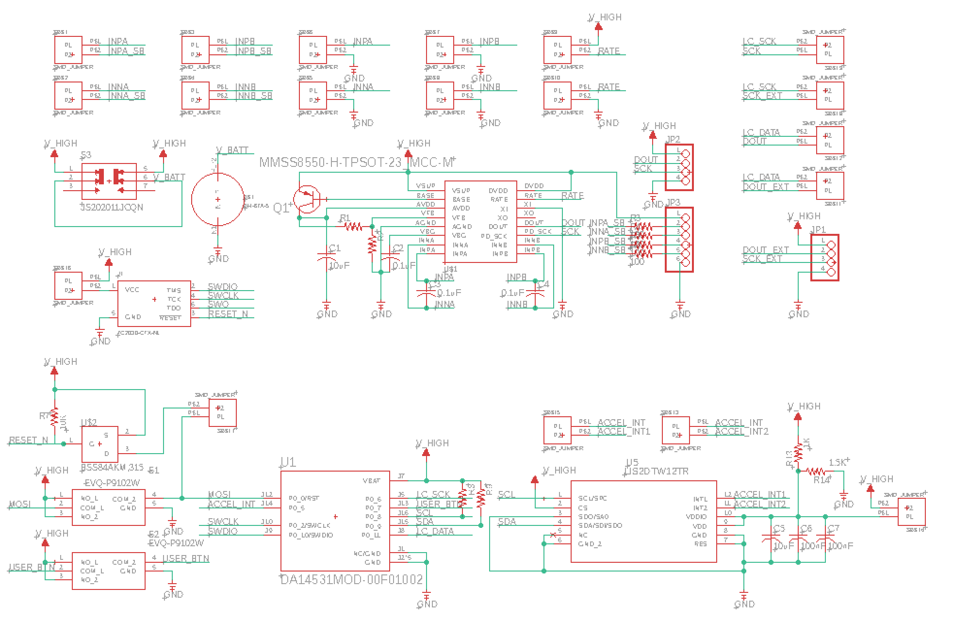
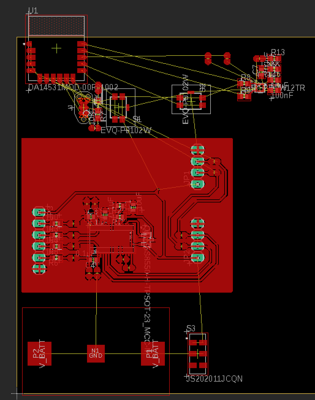
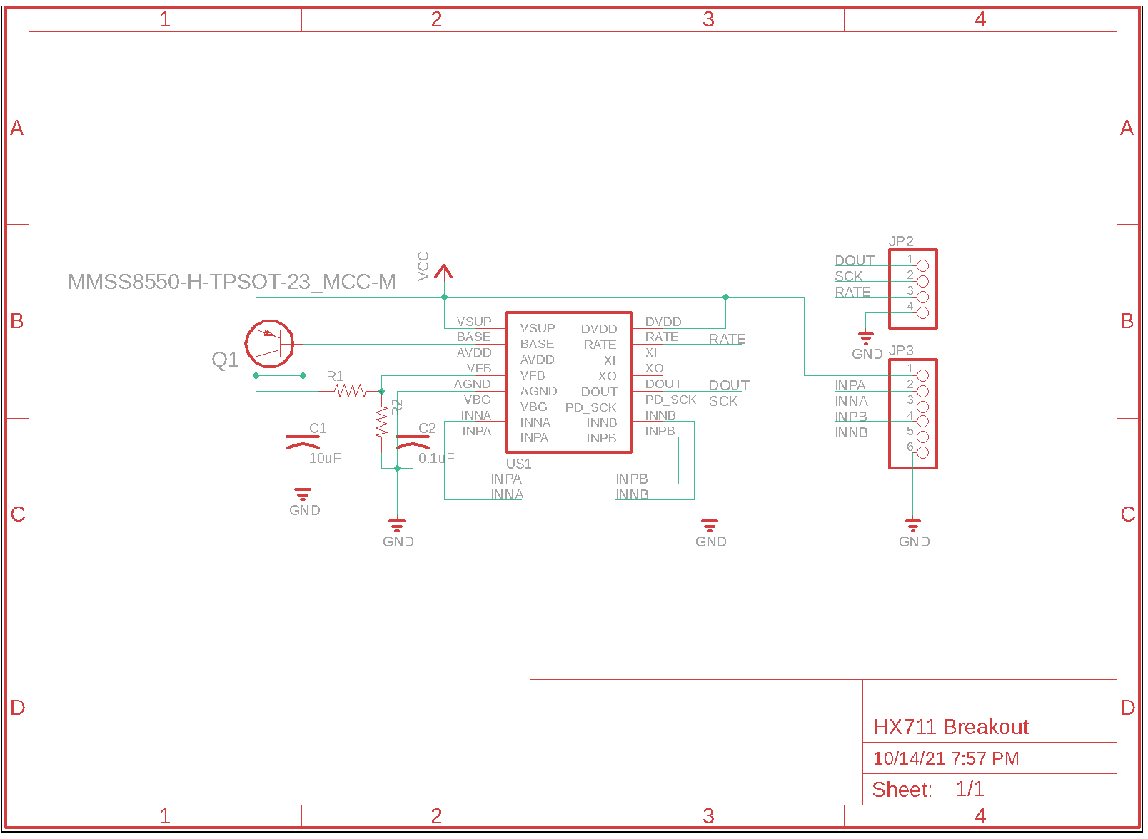
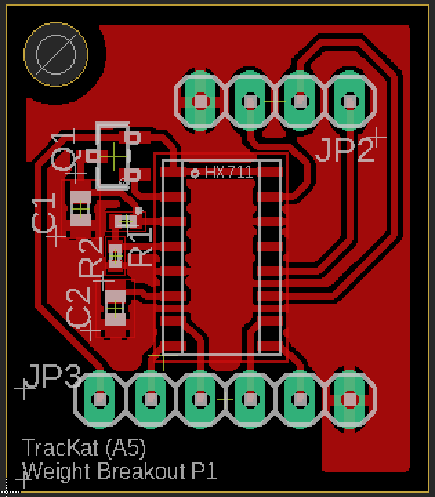
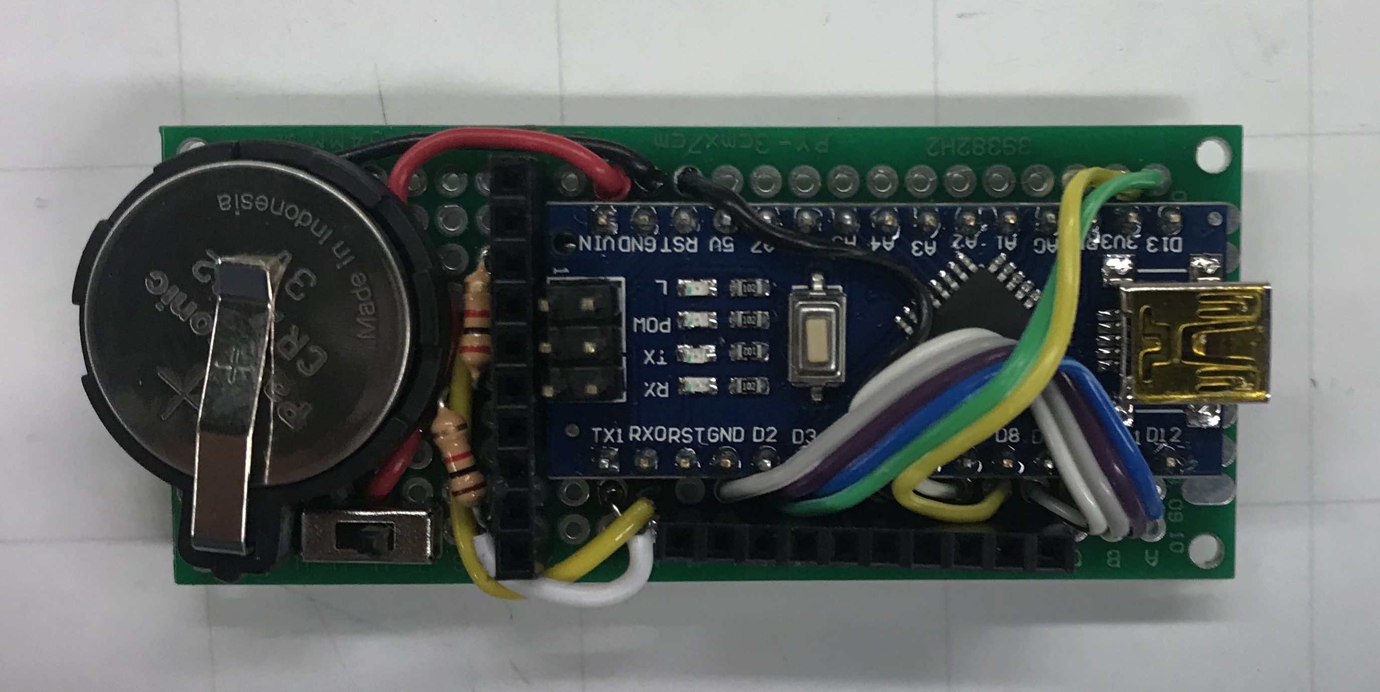
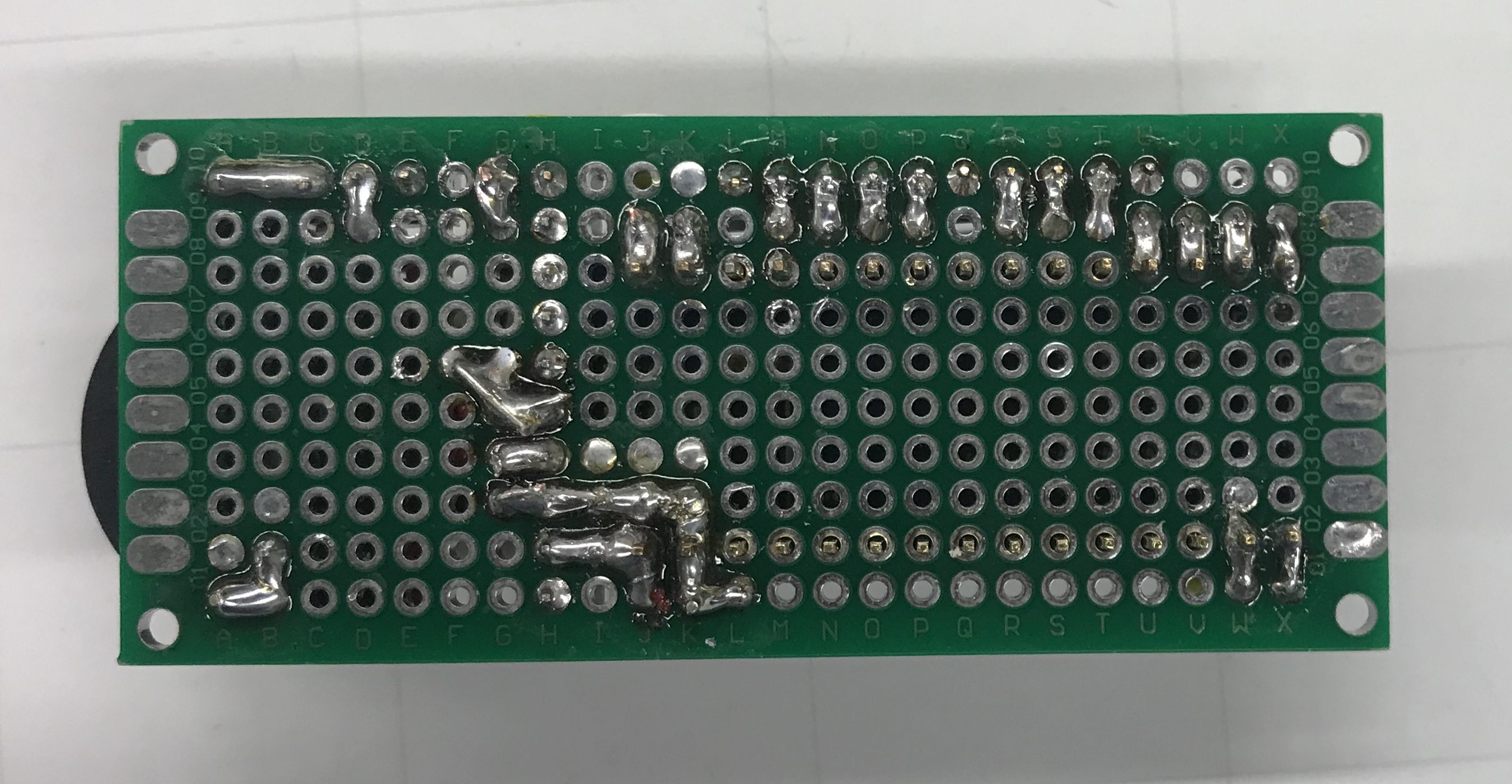
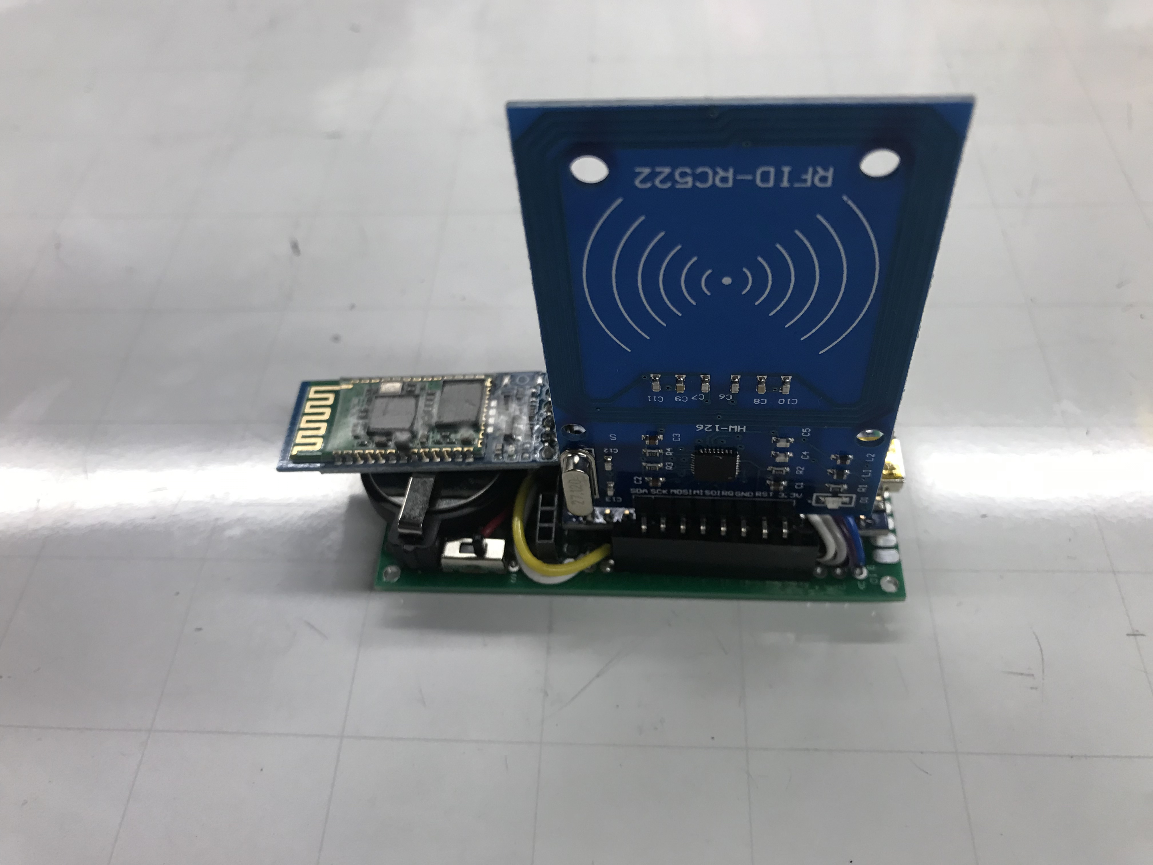
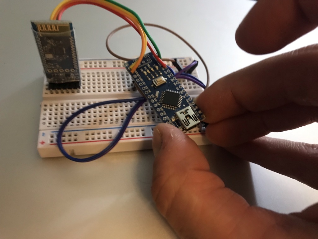
The past two weeks saw major development milestones reached and passed. First and foremost, I finally got the Weight Tag pcb etched and populated!


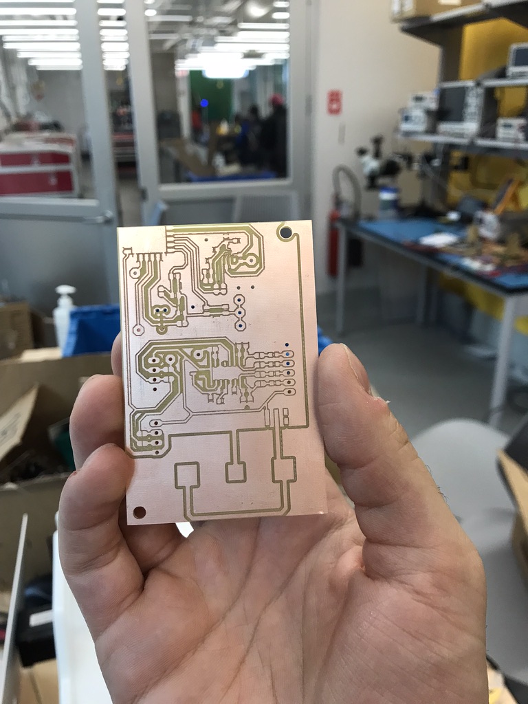
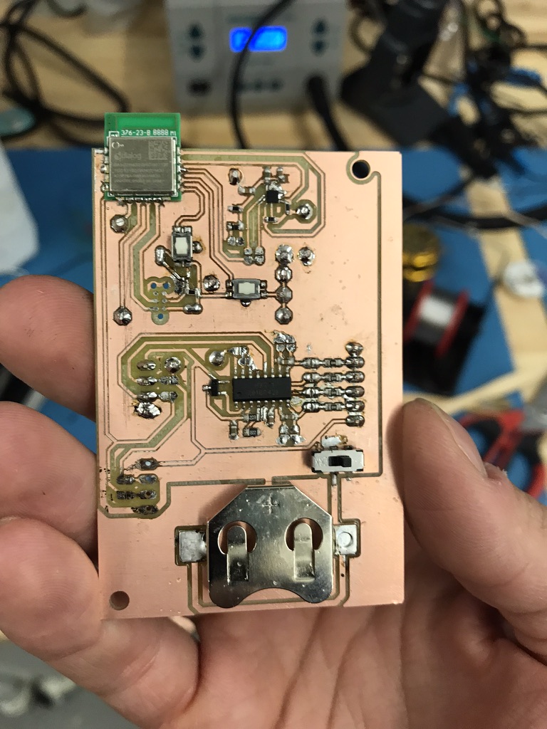
The tag runs our firmware and is powered from a single CR2032 coin cell battery.

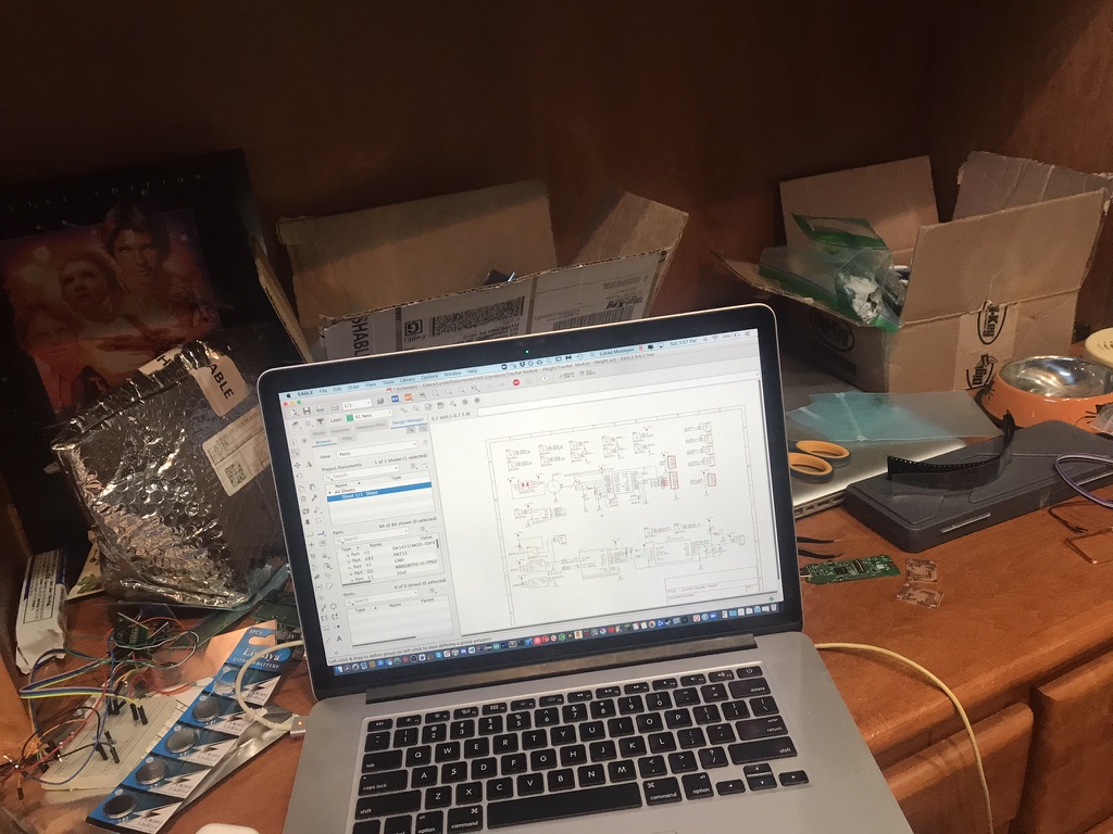
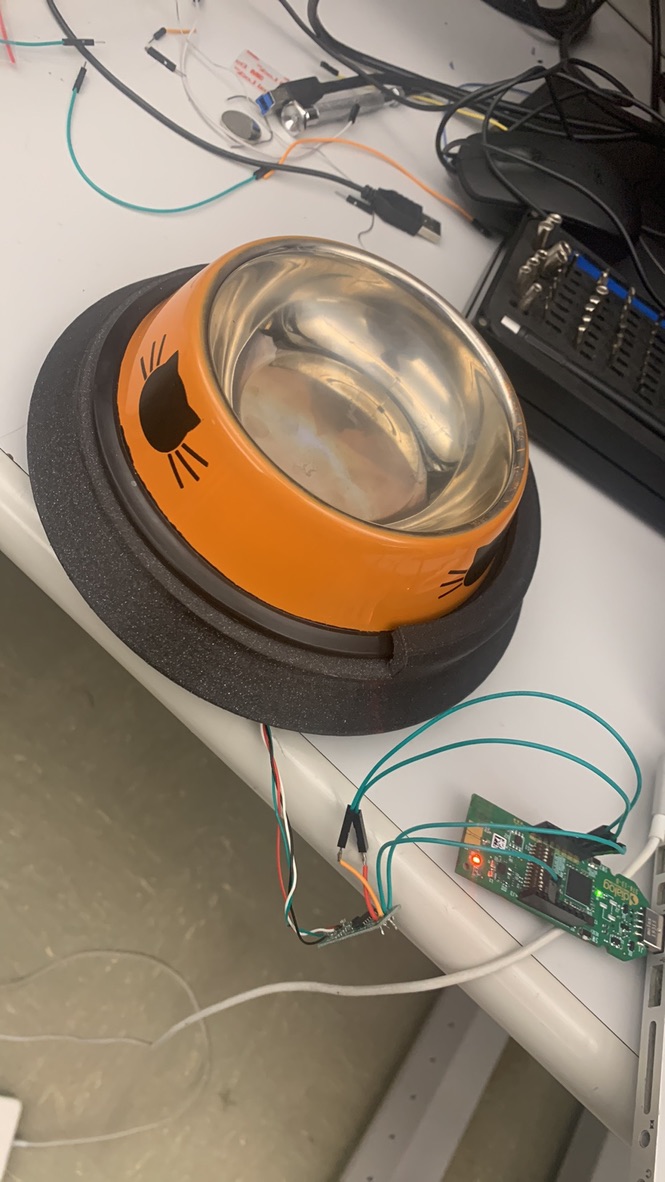
I went back home to New Jersey for Thanksgiving but brought along plenty to work on…it got a bit messy:

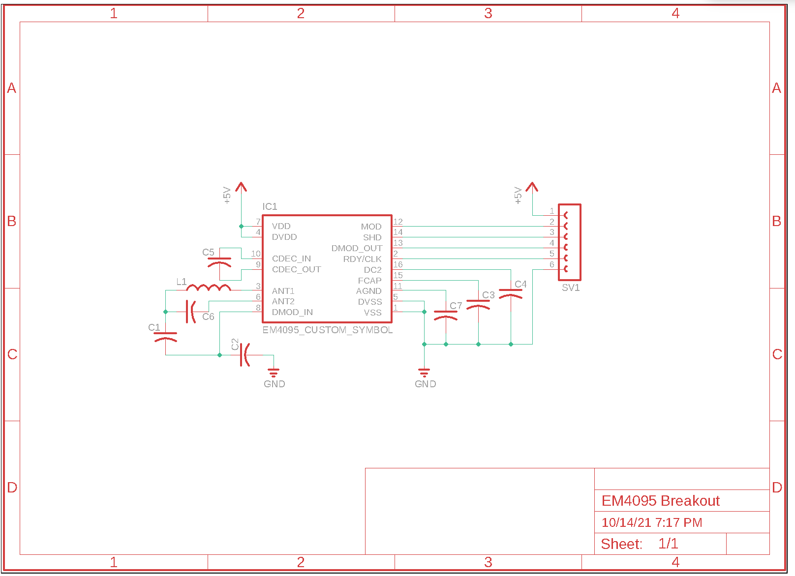
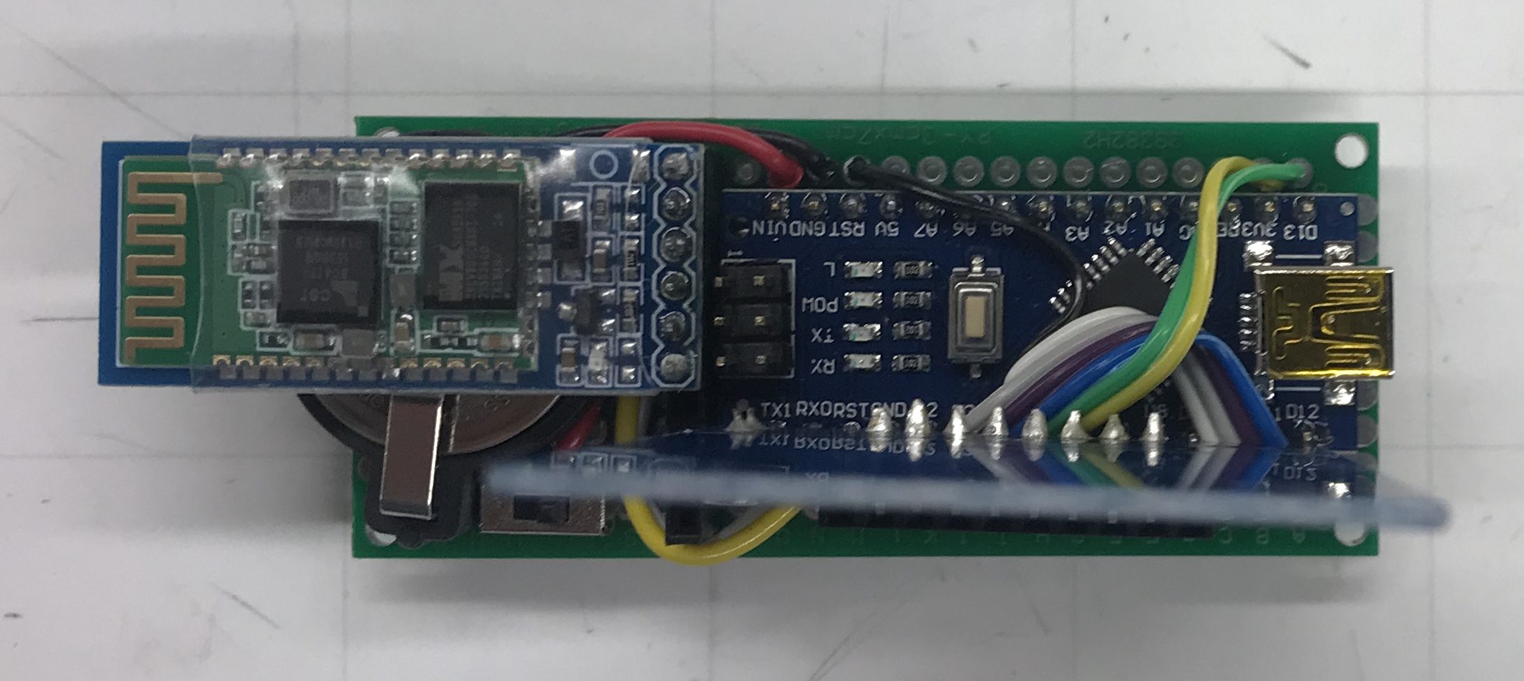
While on break, I primarily worked on the RFID firmware, the Weight Tag hardware (populating a second board), and conducting live tests for our final presentation slides.

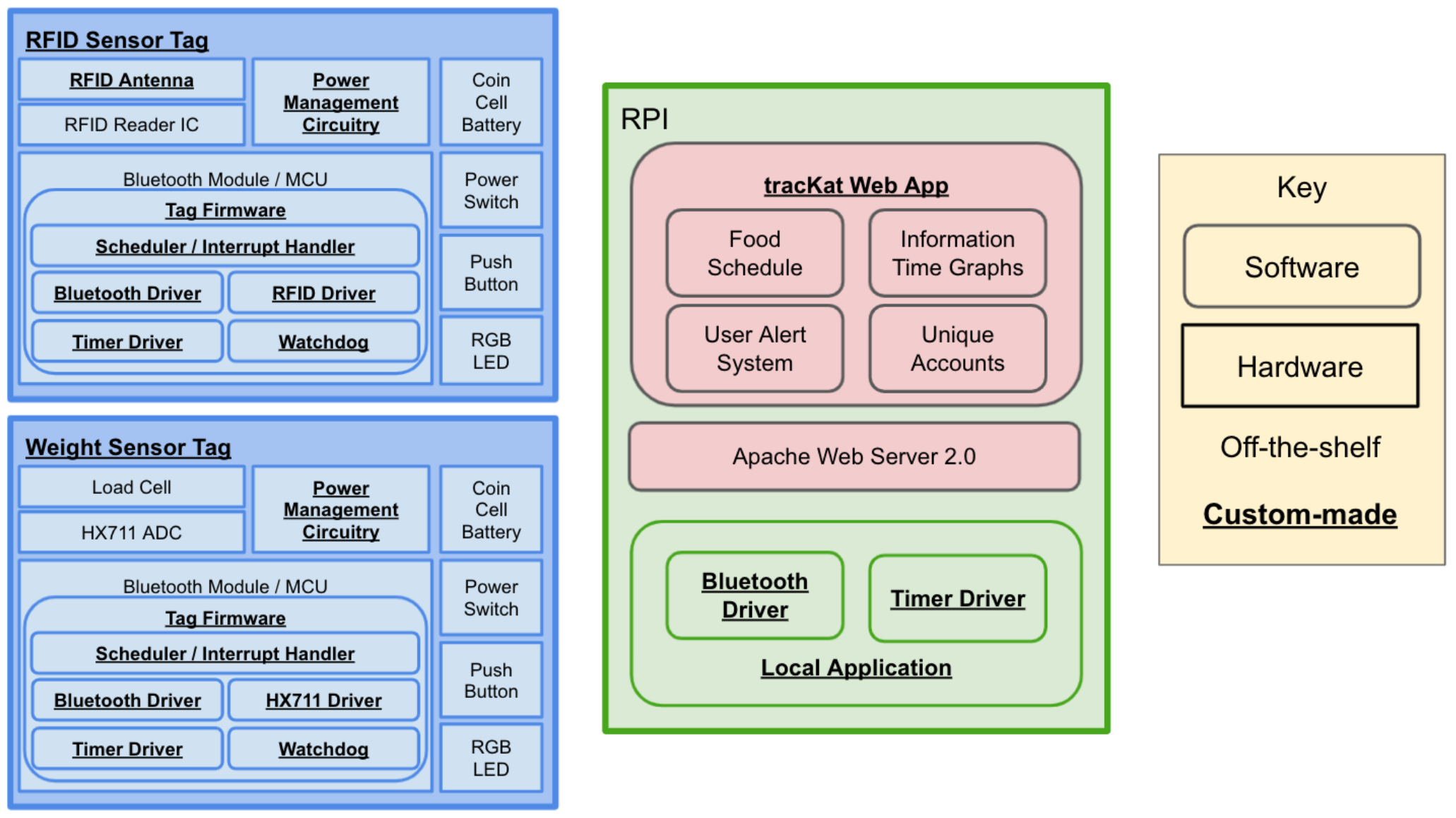
After coming back from break, I helped wrap up the final report. Specifically, I wrote the Solution Approach (slide 2), Hardware (slide 3), Live Testing (slide 7), Results (slides 8 and 9), Design Trade-Offs (Slide 10), and Lessons Learned (Slide 11). I also helped on the Project Management (slide 12) and Public Demo (slide 6).

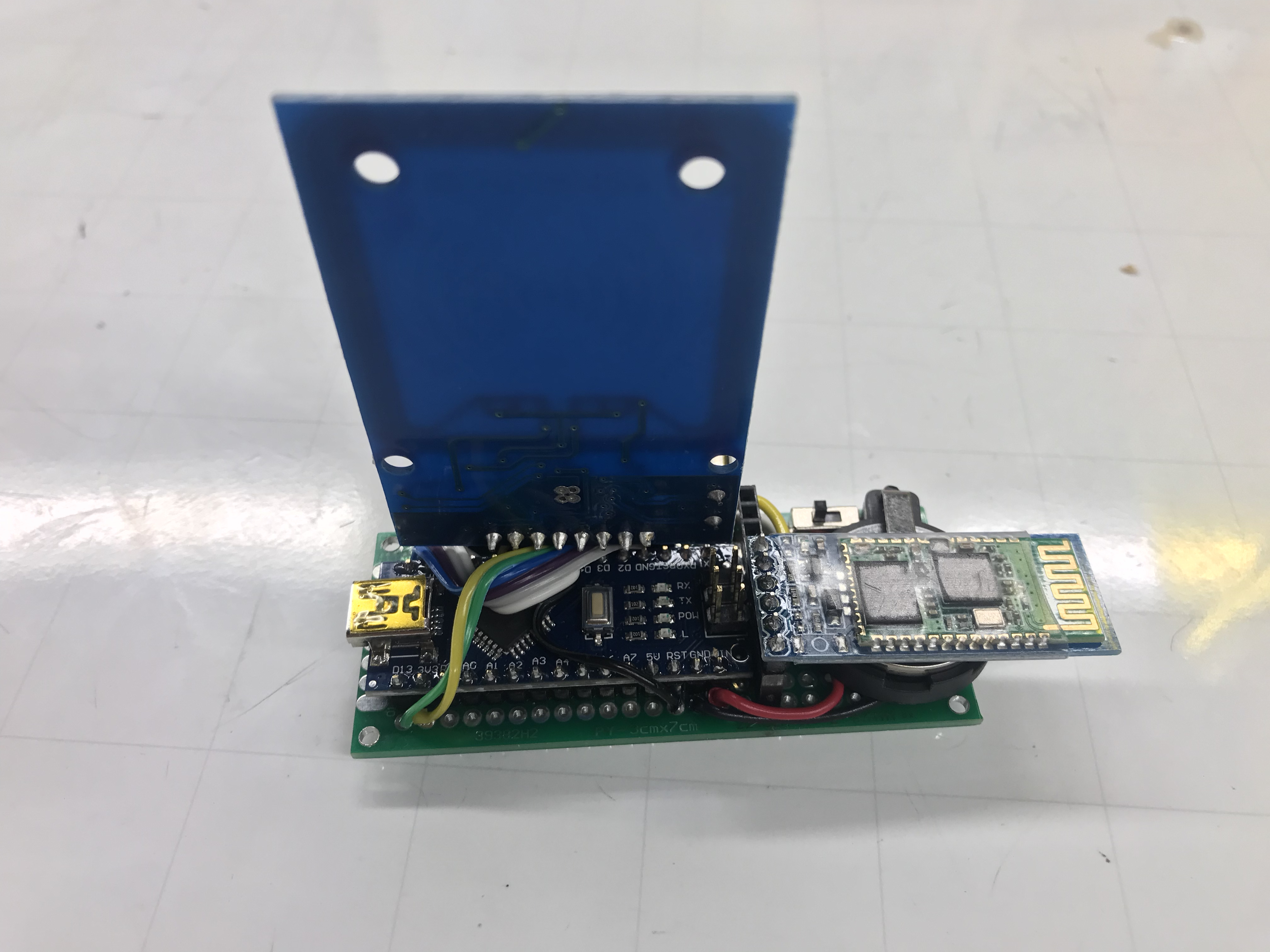
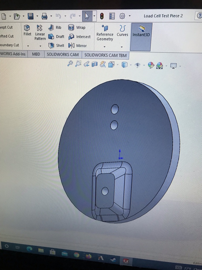
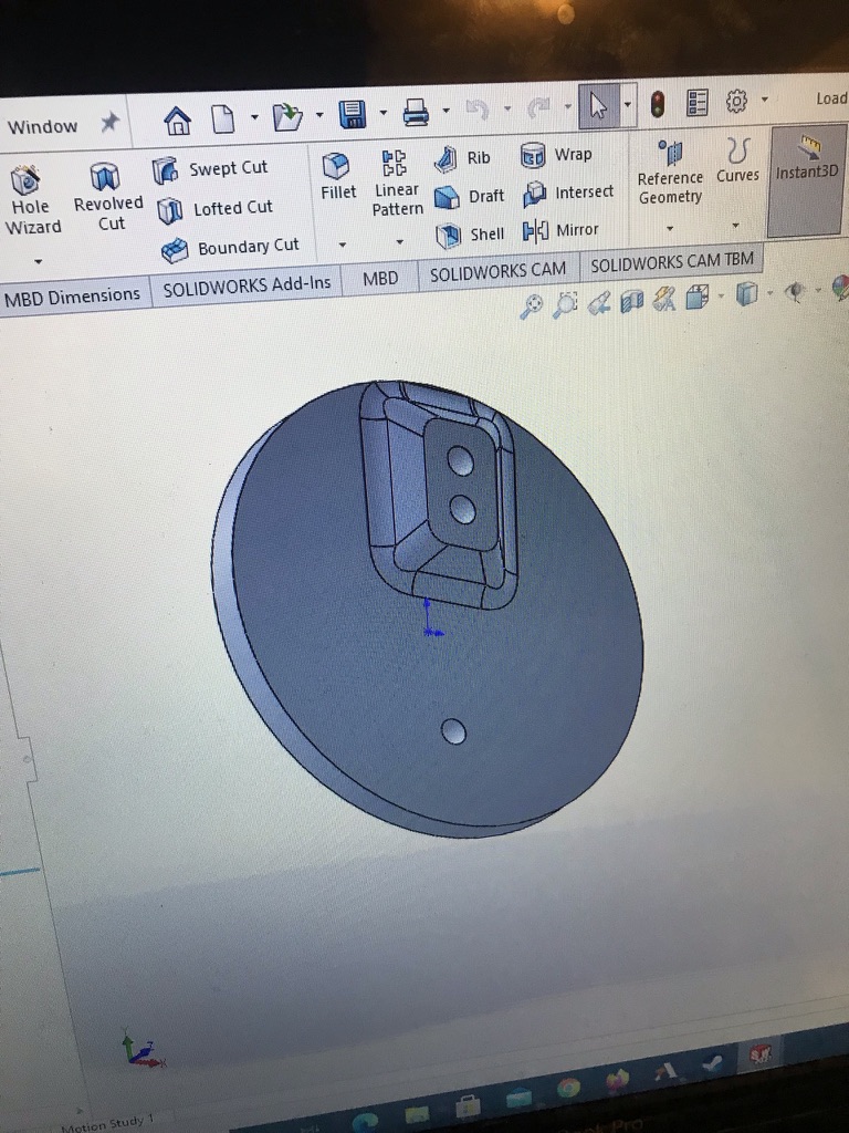
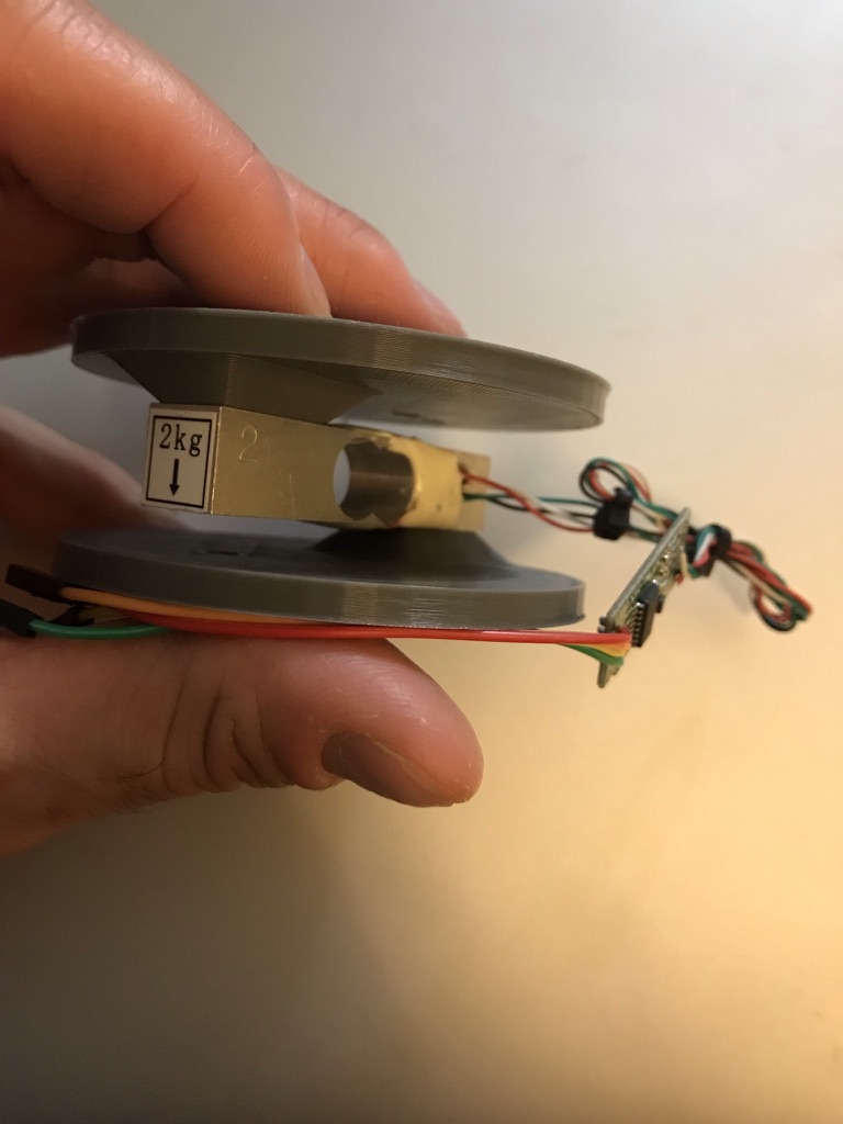
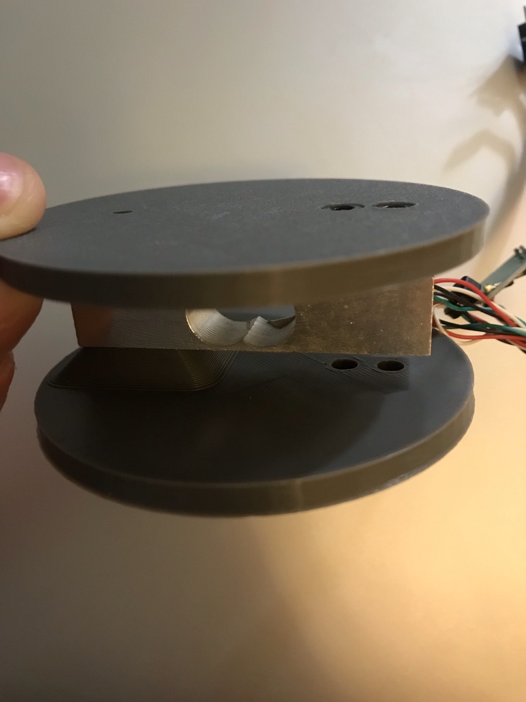
After our final presentation, I took some time to design the enclosure for our weight tag from scratch and printed it out (bottom piece is printed but currently locked in Roboclub :P):


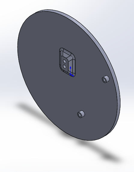
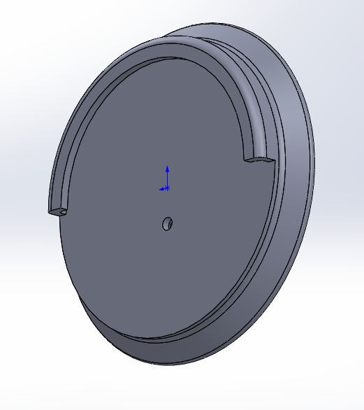
The enclosure’s top features a lip to snuggly secure the food bowl and a skirt to push any water or kibble that falls out of the bowl away from the electronics housed underneath. The bottom plate has mounting holes for our custom weight tag offset from the base to add further protection against water damage.

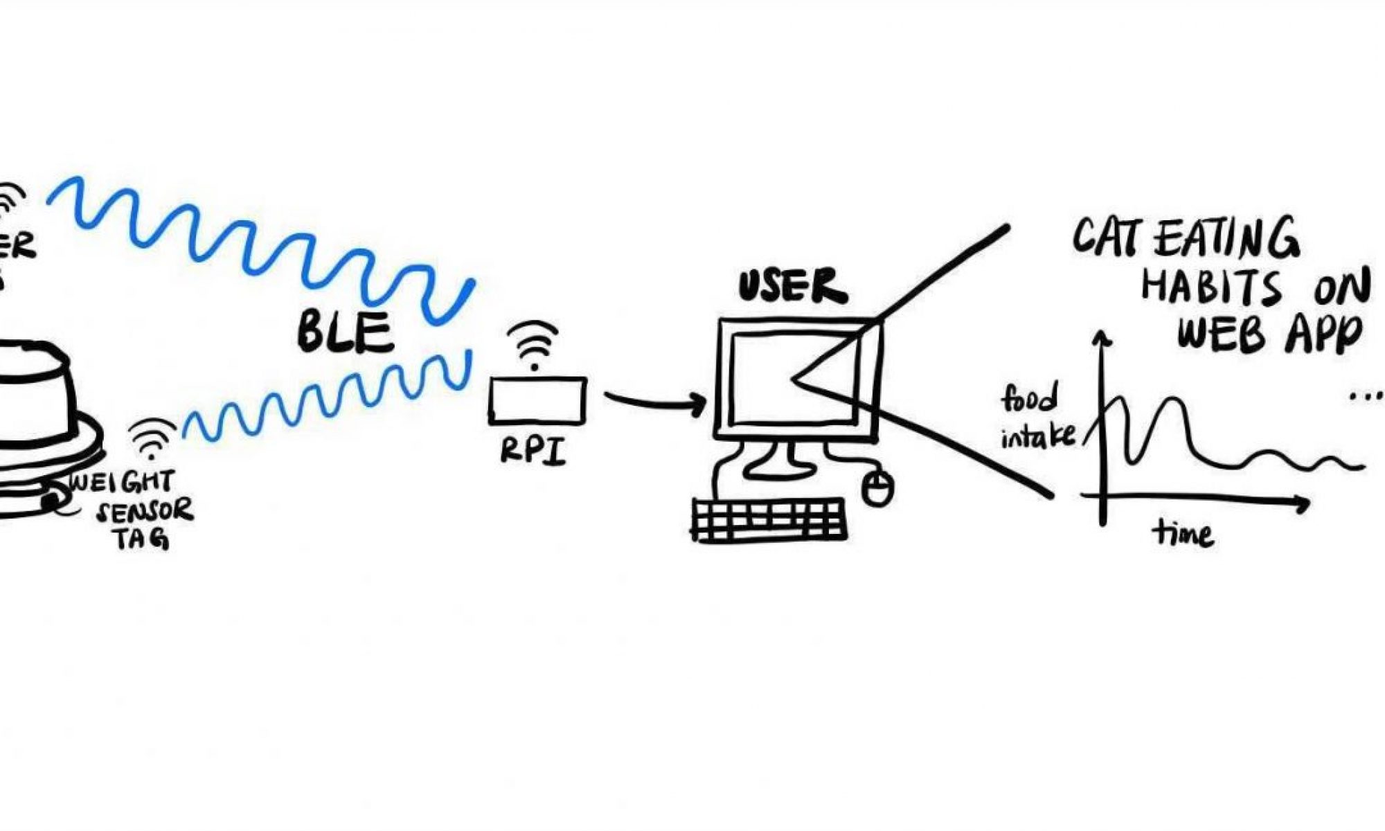
To wrap up the week, I debugged and fixed some issues with the characteristic values from the tags not being seen by the RPI over BLE.

With the weight tag just about fully finished, my goals for next week are to wrap up RFID and prepare for the final demo. Time is tight, but at this point I am confident we’ll have a solid project to show off.


Lucas’s Status Report: 11/20

This week finally saw the completion of the full Tag to Hub pipeline. I mainly worked on the firmware required to make the DA14531 board report load cell values as a characteristic (a value sent through the bluetooth protocol to the rpi hub). I also developed the load cell weigh sensing to save values only if they surpassed a preset threshold. Next steps are to run a hardware timer that will report timestamps of when new weight values are added to the array of values – these represent individual “eating events” which the system will count and check for consistency.

Finally, I re-designed our pcb’s based around the now-available DA14531 Bluetooth module ( basically a small package consisting of the DA14531 chip, a 1 MB SPI Flash, and an antenna with a pre-made CLC filter). The schematics are fully finished and the layout is “near-done” (as in: I expected to etch it out today but it’ll have to wait until tomorrow). Making PCB’s in-house means they have to be CNC milled – i.e. they can only be single-layer boards. Not having multiple layer to route through definitely adds to the challenge of creating a complex, multi-component design, but I’m managing it.

I expect to have a functional pcb in my hands tomorrow (Sunday).

Lucas’s Status Report: 11/13

This week I mainly worked on getting the demo fully ready and then continuing to build and polish from there. I was responsible for the hardware portion of our demo, which was a bluetooth enabled weight sensor. The device featured a load cell housed in my custom enclosure connected to an HX711 breakout board, which in turn communicated with our DA14531 USB Dev Board to read out weight values. Our demo was essentially a not-yet-fully-integrated version of our weight sensor tag.

The basic functionality of the demo involved a custom driver for the HX711, which would begin pulsing a system timer upon bluetooth connection being established. The driver waits for the “value ready” signal from the HX711 and then pulses out 25 rising clock edges. In turn the HX711’s shift register shifts out a 24 bit weight value which is then interpreted by the dev board. If the value is above a preset threshold, the dev board lights an indicator led. I primarily included the indication led to demonstrate threshold values because the device’s UART does not seem to be functional. Because it cannot therefore display values it receives in real time, I used the led as an alternative.

On top of firmware development, this week also saw big strides on the hardware front. The PCB’s are almost fully finished, and I have now designed, etched, populated, and successfully tested versions 1 and 2 of our custom load cell breakout.

The breakout board has several benefits over off-the-shelf breakouts, primarily in terms of flexibility. I included a number of custom  designed solder bridge pads that can be connected or disconnected to select between a number of features the HX711 chip offers. The most important of these is the RATE selection line – grounding it versus tying it to VCC selects between 10 and 80 Hz data rate. Leaving both rates as an option allows for testing which pulls less power and thus gives us more room for customization along the lines of power savings vs. speed as we polish the sensor tag design.

No description available. No description available.No description available.


I also worked on getting the PCB’s finished and ordered. I finalized the parts list and finally had the order placed. Unfortunately, I encountered a silly mistake late in the design process – we needed one more GPIO than the DA14531 chip had available! Essentially, the problem came from a late decision to have the RFID sensor tag run an accelerometer which would sense vibrations caused by a cat accessing the food bowl. Upon detection, the sensor tag would turn on the RFID reader to scan the cat’s ID chip. This design decision centered on the key point that the accelerometer would be orders of magnitude less power hungry than the RFID reader (as little as 10µA versus upwards of 200mA). In order to run the accelerometer in conjunction with our RFID reader, I figured we’d only need two GPIO lines to support the I2C protocol, but it turned out that the accelerometer also had a mandatory interrupt line in order to function.

I am now spec’ing out an I2C GPIO expander to allow for the additional I/O. Once that is done, I’ll have the PCB’s fully ready and ordered.

Lucas’s Status Report: 10/23

This week I focused on a combination of getting firmware rolling, wrapping up PCB part sourcing, schematics, and layouts, and working with the team on integrating the full communication pipeline from BLE tag to hub to web app.

Last week, I focused way too much on setting up the ble tag firmware development environment and finishing the PCB’s at the cost of working more on the design report – I wrote the abstract did a little bit of editing, but little more than that. Luckily, several of the system diagrams and notes on hardware tradeoffs I made before came in handy in the report, but I definitely should have actively worked on it more.

What that time went into was firmware development, hardware development, and parts sourcing. Firstly, I jumped through several painful hoops getting the Keil development environment, Dialog SDK, and SmartSnippets Toolbox all working on my Mac (after a lot of time spent on stuff not working properly, I bit the bullet, bought Parallel, and set it up on a Windows VM). The result is that I can actively develop firmware for the USB dev kit as well as our future custom tags. With the LED blinking, I have the hello world I wanted to get. The tags can actively be run from a debug build and I confirmed that permanently flashing them also works.

On the PCB front, things are not as far along as I’d hoped, but still steadily moving along. The parts are all selected for the weight and rfid sensor portions, and I have completed the design of breakouts for the main chips. This just leaves the primary tag pcb left, with just a little work left to be done on getting the SPI Flash memory chip and SWD JTag done.


Finally, I used the PCB mill at my job’s office to get the prototype breakout boards cut out:

It’s great to actually have these things physically in my hands!

No description available. No description available.

I have been actively chugging through datasheets for the DA14531 ble/mcu, the spi flash, the accelerometer, the rfid chip, and the hx711 adc/amplifier. Next week, I’ll aim to have the ble usb dev kit reading values from the HX711 (connected to the load cell). In other words, next week will see the weight sensing up and running and (hopefully) displaying live data in the web app.


Lucas’s Status Report: 10/9

This week mainly saw me helping the team write the design report and develop the tag pcb schematics and layouts. With the prototype schematics just about done, I am now moving on to finishing the layouts and getting the pcb’s and parts ordered. The delays to the hardware schedule currently present a pretty large risk to the project, so I am working hard to close the gap.

I also worked on getting our prototypical RFID tag antenna built using the custom 3D printed ring.

I will primarily be working on the design report with MeeDm and Tarush throughout the first half of this week while the second half will see me getting the pcb’s ordered. If there is time, I will also be working on getting Shelley operational.

Finally, the DA14531 development boards I ordered have arrived meaning that I can get firmware development properly underway. This week I will aim to at least get a “hello world” program successfully flashed to the dev board.

Lucas’s Status Report: 10/2

This week mostly had me tied up by a pretty tight crunch at work, but I still got through most of the goals set out for this week. These were mainly to get the demo hardware working as well as finalizing the BLE module trade study and selection. I also worked with MeeDm and Tarush on the Design Proposal presentation.

One of the most unexpected hurdles in choosing the BLE module ended up being totally unrelated to technical trade-offs: logistics. As it turns out, the world is experiencing a really bad semiconductor shortage, and the supply chain for ic’s and mcu’s has been left in a rough state as a result. Almost all the options I considered ended up having to be scrapped due to either a development board or module not being available – in some case’s the ic itself was out of stock with lead times ranging from 18-52 weeks!

In the end I settled on the DA14531 BLE module. The primary points I considered were power consumption, ease of development/implementation, and supply chain; the DA14531 knocked each category out of the park. This IC features an ARM Cortex-M0+ processor and achieves absolutely top-of-the-line power consumption specs of under 22µA/MHz clock rate and 240nA hibernation mode. Dialog Semiconductor provides ample documentation and has an active forum – critical to ease of development. Finally, the IC and its accompanying evaluation boards are in stock and readily available from a number of distributors, including DigiKey. With the order placed, my focus will now shift towards getting the prototypical schematic and layout finished for the BLE tags.

Speaking of tags, I also worked on the Arduino-based demo hardware and completed assembly of the RFID bluetooth tag:

The tag features a coin cell holder, headers for an HC-05 Bluetooth module and RC-522 RFID reader, and power switch. It’s quick, it’s dirty, and it works. Along with the load cell based weight sensing tag, this RFID tag will allow the team to develop and test the full project pipeline on real hardware without waiting for the actual BLE tag pcb’s to be spun up. Next week I’ll wrap up the demo hardware by putting it in a nice, custom-made enclosure. I’ll work with MeeDm to get it connected to the RPI and I’ll work with Tarush to have the web-app display communications between the demo hardware and the RPI hub.

As I learned the hard way this week, a new risk to consider is time commitment at my job. Going forward I’ll have to actively temper my responsibilities there with my work here.


Lucas’s Status Report: 9/25

This week was a little slower on development than past weeks, but we still all chugged along.

I presented our Project Proposal on Monday and, along with everyone else, filled out feedback forms on the Monday and Wednesday presentations. It’s so exciting to see all the interesting projects the capstone teams are working on this semester!

Here’s the raw presentation (it’s a little quiet so check your volume):

I mainly focused on re-printing some of Shelley’s (our robocat test dummy smarty) parts. The main issue we ran into was that the original parts we printed suffered from “elephant’s foot” – basically the first layer was pressed down too much by the extruder head and expanded out too far to be within part tolerances. I recalibrated my printer and (after a terrible failure) got the fresh parts done around Friday.

I had to leave for Delaware on Friday morning, so Shelley will have to wait until this upcoming Monday to be fully assembled.

Before leaving, I also worked on putting together the demo parts – mainly soldering the HX711 breakout, arduino nano, power switch, coin cell holder, and other similar components. I also grabbed some cords from Roboclub and got the our Raspberry Pi set up with raspbian, net reg, and a static ip address.

Next week will see Shelley up and running (literally), the demo working, and apache web server hosting a basic “hello world” web app built in django. I’ll also wrap up the trade study on BLE modules, select one, and begin work on the schematic for the prototypical Tag pcb.

…i’ll also have to clean up our bench space


Lucas’s Status Report: Week of 9/18

Hello World!

The main team goals for this week were to finalize technical requirements and write up course documentation (gantt chart schedule, proposal slide deck, website, etc.). I mainly worked on the solution approach, preliminary system diagrams, and technical requirements.

TracKat Proposal System Architecture I also researched BLE modules, RFID parts, and weight sensors, and worked with MeeDm to conduct a trade study of using BLE versus WiFi. We ultimately settled on the BLE standard because of its superior power consumption and reduced implementation complexity. I researched the benefits and trade-offs of sensing weight via load cells versus force sensitive resistors – for our use case, the much higher accuracy and granularity achievable with load cells makes them the clear choice.

Throughout the week, I scrounged up free parts from the Robotics Club and Ideate Physical Computing Lab in order to spearhead getting a demo of our system running as fast as possible. I got basic RFID and weight sensing working with Arduino Unos and Nanos and will have Bluetooth ready early this upcoming week. I designed a simple load cell mount in Solidworks and 3D printed it, and will work on getting the whole demo together into a clean package this upcoming week.

Load Cell Mount 2 Load Cell Mount 2

Assembled Load Cell 1 Assembled Load Cell 2

Arduino Nano Bluetooth Module

Finally, our testing strategy initially assumed we would purchase a couple stuffed cats and implant them with RFID microchips. Instead, I ended up stumbling on Petoi, a company founded by some CMU grads. They made a project called OpenCat, an open source, Arduino based robot cat. Of course I had to print it out, and I found all the necessary parts (microcontroller, ultrasonic sensor, hobby servos, motor driver, and rf receiver) in RoboClub! Next week will see this pile of “managed chaos” transformed into our test cat, Shelley.