Team Status Report for 11/13/21

This week we finished up the interim demo and continued testing to improve the propulsion system and computer vision. At the end of last week, we finished integrating the Raspberry Pi with the Arduino in the prototype we have been working with. On Sunday we finished the integration phase by calibrating our software to respond to a circle target placed below the device (where the camera is pointed). We found that the camera feed was off center. That is, the center of the frame was not exactly directly below the camera. This would have been an issue later because when the target is near the frame’s center, we want to fully deactivate the motors. Another issue was that we had to assign one of the motor directions as the origin, or 0° point. As it was, the direction derived from the computer vision was not synced to the direction of the motors. To correct for both of these problems we added an offset of about 30° to the angle and 200px to the center inside the circle detection script. 

After the demos were completed we prioritized working on our propulsion thrust because it was not enough to get our device moving enough. We fabricated another thrust testing apparatus to measure the amount of thrust being produced. 

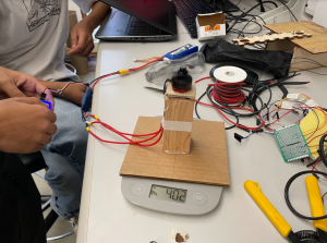
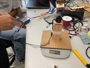
The propulsion is exerted down onto the scale and originally measured 330 grams. We theorized that the low gauge of our wires was inhibiting current from the ESC to the motors. When we replaced these connectors with thicker ones, the thrust was 400 grams. Another measure we took was adding 600 grams of gravel to the inside of the device, as a weight. This was meant to increase the tension in the parachute straps, to reduce swinging. We did a drop test with this setup and the swing was reduced, but our propulsion was still insufficient. We found after returning to the lab that the battery was low on charge. We will be trying again with increased propulsion tomorrow, weather permitting. 

Thrust test with low vs high gauge wires:
Lastly, we held the camera over the Pausch bridge to see if our detection would work after all the changes we made over the past two weeks. This week, we reduced the shutter speed to reduce motion blur. This change increased the detection rate from about 35% to about 90% in the indoor setup. We found that the circle was too small in the camera feed when held from the 43’ height. We are working on two avenues to fix this. One is to print a 2-meter circle instead of the 1-meter target we have now. The other method is to enlarge the usable portion of the fisheye image or correct it to be equirectangular. Our mitigation strategy for this area is also to start testing on a USB webcam, which will altogether remove the issues we face with a fisheye lens, but add more weight. 

Note the lack of motion blur with the faster shutter speed, both frames taken mid-swing:
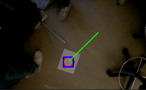
1500 microsecond exposure time
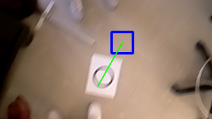
9995 microsecond exposure time (circle is not detected!)
Lahari’s Status Report for 11/6/21

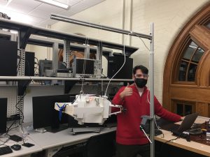
This week I improved my CV  target detection code and helped the group with more drop tests and some integration tasks. For integration we finally combined the propulsion system inside the housing with the PWM generation code that Daniel prepared and the CV code that I worked on. Daniel and I built an apparatus, pictured in the team report, to hang the device from for our demo. I uploaded my code to the Raspberry Pi, and adjusted it to the new camera. The fish eye lens was different from that of my laptop camera so I had to reduce the perfectness parameter and increase the maximum radius from 30 to 50 pixels to make it visible at the distance fit for our use case.

The earlier part of the week I spent making my CV more robust. I did a number of things to address problems like false circles and misattribution of the target. These changes have made the algorithm more robust, and affected the latency minimally. We measured about 6fps before and 5fps after.

  1. I performed HoughCircles on a thresholded image instead of the original grayscale image. This means the image was changed to binary, with pixel values above a certain value turned to 255, and the rest to 0. Our target is black against white, so circles where the gradient is less will not be present in the thresholded image.
  2. When the circle is lost, most likely due to motion blur, the last known location of the target is stored.
  3. When there are multiple circles, we choose the one whose center is the least Euclidean distance from where the target was last found.

Daniel’s Status Report for 11/6/2021

This week, I worked primarily on helping the team test the device with more drops, as well as implementing the vectorization algorithm, and integrating it with the arduino code (which controls the motors) and the CV code (which detects the circles). We then worked as a team to test the full detection-to-propulsion pipeline.


For the drops, we tried various parachute setups (2 vs 3, shorter and longer slack lengths). As usual, I held up the parachutes and let go of the device as Lahari initiated it with the press of a button and Vikram was below to catch it. We noticed a pendulum motion as I dropped the device. We then tried to drop the device, then initiate the motors mid flight, but the same issue persisted. We think this may be a lightness issue, so we will resume drops after the interim demo with additional weight at the base of the device to prevent swinging.

As for the vectorization code, I implemented it in Python, and sent the data over serial so the Arduino can use the values. In short, the algorithm takes in the angle and magnitude of the vector towards the target, from the center of the frame, and computes the necessary PWMs for each of the three motors that will create a resultant vector that is equal to the target vector. After this, we tested the script by connecting the Arduino (which was running code Vikram wrote to receive the PWM values over serial), and noticed a hanging/slowdown using the serial over the USB connection. We then moved to the GPIO RX and TX pins, and using a logic-level-shifter, connected the Arduino and Pi directly. This solved the hanging issue (the serial over USB is prone to slowdowns as it is dependent on the processor frequency). Then, I helped the team test the vectorization algorithm by inputting various angles to the script, and seeing if the correct motors spun up. Since our motors are defined at angles 0, 120 and 240 degrees, we tried these values as well as values in between (such as 60 and 90), and found that it worked as intended, meaning I was on schedule with its completion.


After this, I then worked to integrated the full Camera to Propulsion pipeline by having the CV Python script call the Vectorization algorithm, which then communicates with the Pi over serial. To test this, I placed a circle on the ground as the target and moved it around, checking to see if the angle generated by the CV code was being passed on to the vectorization algorithm, then seeing if the correct motors spun up. With some CV tuning, we were able to get a consistent detection-to-propulsion pipeline, as the circle changes position the motors move accordingly; however, one issue we found that we will fix tomorrow is the relative angle 0 to the camera, and to the device were not matching. This meant that an offset existed between the angles that the device moves towards, and the angle the camera produces . This should be a matter of experimentally deducing which angle is 0 to the camera, which angle is 0 for the device, and matching those. The above was all tested using our new demo setup (described below), as I ran the camera+vectorization script on the Pi and Vikram and Lahari turned the device on or off between tests.

I also helped the team build a testing setup to demo our device for the interim demo on Monday. This involved getting various 80-20 pieces and attaching them in such a way that would allow us to hang the device over a target using string. We tested the setup and found that it was able to hold the device stable, as well as allow it to move a sufficient amount to demonstrate the mobility of the system.

Vikram’s Status Report for 11/6/2021

This week, I worked mostly on the hardware platform for the device, and the Arduino software. We are using an Arduino for now communicating with the Pi over UART in order to control the motors. This is in the interim, and we may remove this in the long term using threads or something similar to allow for continuous control of the motors during flight. The new code took PWM values from the raspberry pi python vectorization code and runs the motors accordingly, and handles I/O and start/stopping. I also worked on a new custom soldered perfboard that integrates all the I/O and PWM cables to make the inside of the system less cleaner, and have it mount to the Arduino so there isn’t risk of disconnecting a cable during flight. I added another power splitter to the power distribution board I made as well, in order to drive 3 ESCs/motors concurrently for the demo.  In addition, I helped during the drop tests this week where we diagnosed some issues with motors causing spin and swing, and are working to address those issues. We believe that adding some weight to the system can help reduce this issue as well. I also helped develop the interim demo test apparatus we want to use to demonstrate our project working in a smaller scenario. We are currently working to calibrate our mounted camera such that the target detection will reflect in motor driving correctly. We are mostly on schedule currently, with basic integration essentially complete for the demo. The final housing got pushed because the interim one is functioning. In the coming weeks, I hope to continue flushing out bugs in the integrated system, as well as verifying that our thrust tests were accurate and that we can reduce the swaying by adding a little more mass to the system.

Team Status Report for 11/6/21

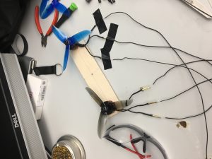
This week, we completed several more drop tests and prepared the interim demo for next week. We inferred from last week’s tests that there was not enough thrust to move the 3 meters that we wanted. Our idea then was to use two motors on each of the three sides instead, to hopefully double the thrust. At a TA’s suggestion, we also acquired larger propellers as another way of increasing the thrust. The thrust tests, done on a scale, showed 600 grams with double propellers. It was approximately 600 grams with the large propellers as well, but these were not meant for the motors we had so they couldn’t be installed properly without vibration.

We did a few drop tests on the double propeller arrangement we put together last week. We repeated the tests several times, each time adjusting for different variables. The first time around, we noticed there was swing so we changed the Arduino code to start after the drop began. On later tests we had to address spin and lack of movement. We were unable to modify the design so that the propulsion system would move where we wanted. This is the area of our project that is the most uncertain at this point. To mitigate risk, the next time we get the chance to do a drop test we want to add balanced weights to the inside of the device. We think that a persisting problem is the lack of tension between the parachutes and the device. With this change movement will not be impeded by swing or spinning. Video

For our interim demo, we set up an apparatus that will suspend our device 1.3 meters off the ground, while we move around a target image of 10cm diameter below the camera on the bottom. This models our actual 13 meter drop height against a 1 meter target diameter. We will show that we can activate the propellers in the correct direction based on the target’s relative location.

Vikram’s Status Report for 10/30/2021

This week we attempted multiple powered and unpowered drop tests. In addition, I noticed in one of the videos that our two parachute configuration was creating a axis upon which our device would sway back and forth. To try and mitigate this, we attempted to add and drop with an additional parachute. While this seemed to remove some of the swaying, the third parachute did not fully deploy, so we weren’t able to reap all of it’s benefits.


Another issue we found was that the power of our system didn’t seem enough to move the drop unit a meaningful amount. We are working to fix this by attempting to add an additional motor to each side, to double the thrust. Hopefully this will address this problem, but may add more complexity as we need to double the amount of motors and controllers, so weight may increase considerably. This is what I will continue to focus on this week. If this works however, we are on schedule. The other concern I had is that with a proper housing made out of a robust material, our total weight will be significantly higher, perhaps putting a restriction on the payload weight we can withstand during a drop.

Lahari’s Status Report for 10/30/21

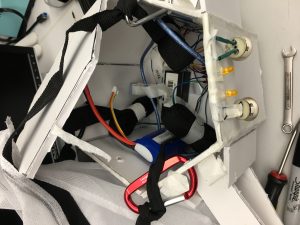
This week we had several tests to carry out. The first was a drop test, which we did again at the Pausch Bridge. This test would tell us whether we had eliminated spin by adjusting the parachutes, and the amount of thrust in our propellers. Last week, I made a few design changes to avoid the spinning that was happening during the drop. I shortened the straps of the parachute and attached them to the body with carabiners. In testing this proved successful by eliminating spin during the fall.  A picture of the parachute attachment now:

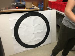
Initially, I tested the circle detection CV using a small image of a circle. Adjusting the parameters of the script, I found a range and line thickness of a circle that would make it visible. I scaled this up linearly to estimate we need a target diameter of at least 1 meter with 10cm thickness. I then printed the 1 meter circle piecewise on several letter size papers and stuck them to a board (pictured in team status report). We tested the large circle and found it was detected at a range fit to our use case, i.e. it was detectable close up and from 43 feet away (the height of the Pausch Bridge).

Team Status Report for 10/30/21

This week we improved on the drop test from last week, the problem was that the device spun during most of the descent and the parachute ropes twisted together. To fix this, we shortened the ropes and mounted them on opposite sides of the top. This solution would ensure that the parachutes were separated during the whole drop. Spinning would otherwise interfere with our perception method, which ultimately determines the relative angular position between the device and the target. When we tested this version on Monday there was no noticeable spinning. 

We then shifted our focus on movement from our propulsion system. We wanted to see how far the propeller at full thrust would move the device. Wednesday was more appropriate for the lateral distance test, because it was not windy. By this time, another set of parachutes had arrived, so we added a third parachute to the body, so the drop time would be longer. The test showed an additional parachute did not achieve this. We would like to test this a few more times before we reject this option, especially because there is more weight that needs to be added, including the payload and extra propulsion. 

At full thrust, the device could not move three meters laterally, a key technical requirement of our project. We decided that each arm of our device should have two propellers instead  of one. We already had an extra motor, ESC, and propellers, so we put double propellers on one of the arms. We plan to test the new thrust capability on Monday, and decide whether to order more parts.

Meanwhile, we conducted a few tests on the circle detection code. We found the 1m diameter circle (pictured below) was detected between 48 feet and 10 feet of distance. It is approximately the same indoors and outdoors. We plan to find the angular range of detection at a few fixed distances next week.

Daniel’s Status Report for 10/30/2021

This week, I mainly helped the team complete more tests to understand how our device behaves under its proposed use case. We noticed during our last tests that a lot of spin was induced from the unsynchronized dropping of two people letting go of the device. As a result, we decided one person should drop it. During each test, I held up the parachutes from their center, held the device over the edge of the Pausche bridge and waited for Lahari to initiate the system using the buttons we installed. Once she pressed it, I waited for the motor to spin up, and let go of the parachutes once it was on full thrust. The spin issue was solved, yet we found that there was insufficient thrust.

To fix this, we are going to add an additional motor to each side. After Vikram cut out a new piece of wood that has enough space for two motors, we worked together to measure various distances to ensure the motors were equidistant from the middle mounting point, as well as to drill the necessary holes for mounting. I then drilled the holes and attached the motors. To test both motors working at the same time, I suggested we use the lab clip wires with banana plug ends to quickly prototype a splitter without needing to solder anything just yet. Then, we worked together to hook up the system. Finally, as Vikram held the splitter, I held the motors and Lahari held the wires in place, I turned on the servo tested and we found that the two motors worked together. As for my vectorization algorithm in regards to this change, I will simply feed in same PWM duty cycle to both motors on any given side since they are both pointing in the same general direction, so the output should still remain as 3 PWM duty cycle values.

Additionally, I also helped the team draw a circle to test the circle detection algorithm at a larger scale. We tied a string to a sharpie, and while Vikram and Lahari held the string in place, I drew on the foam-core, creating a circle as the string acted as the radius (of 0.5 m based on previous calculations described in the past based on scaling up the detection of a 5 cm radius circle from 1 meter away). Due to the uneven nature of this process, our circle was not perfect, and the resulting edge was too thin (even after we filled it in). To solve this, Lahari then printed a perfect circle with a much thicker edge, and glued it to the foam-core. I then ran the python detection script on my laptop, holding up the camera as Vikram moved the circle further and further away. At first, we noticed the range was no where near our required 40 feet range. I noticed the camera quality was set to 640×480, so I proposed that we change it to 720p (1280×720). We tested this both indoors and outdoors, and found a maximum detection range of around 50 feet, which fits our use case.

Vikrams Status Report for 10/23/2021

Last week we focused on making an MVP housing out of foam core and populating it with a few components needed to do thrust testing during a drop. We had our first test with it last week, which failed due to spinning, and hope test again next week. We also performed tests that showed that our directional antennas were not a viable perception method because of their lack or resolution and inability to tell direction with enough accuracy. This involved around in a fixed radii and seeing if the antenna could discern if the beacon was in the “center” of it’s beam path.

This week, I focused on improving the state of.our MVP, with new code for our Arduino test platform, an ultrasound sensor to detect when to stop when our device is above the ground, and a new protoboard where many of our connections were soldered in order to make sure everything is secure now in the event of flipping or spinning. This new board houses I/O in the form of buttons to start and reset the motor spinning up process, in addition to the ultrasonic sensor. Additionally, I’m starting to model our new design for the housing that is based on the hexagonal shape that we prototyped out of foam core. This will hopefully be lighter than our original 3d printed design, and easier to manufacture (time-wise) as well. Some key issues we found with our original design was the print time and the estimated weight in PLA plastic that it would take on. The next steps are to use this updated test platform for another powered drop test, and hopefully for a perception test with our new camera system soon. This camera system will detect a black and white marker placed on the ground and use that to do it’s direction-finding. This way the control method doesn’t have to change much, just the perception method turning an image into a direction to travel in instead of an antenna array. This will hopefully allow us to do more fine-grained control as well, should we need it. Currently, we are on schedule and the new and updated housing will be continued over the next week in order to have our final build housed in a weather-proof container. The indicator LEDs and I/O buttons should also make setting up/ using our system significantly easier.