This week I got the staff fabrication done! I did two iterations of CAD designs that I 3D printed in the ideate lab, and I took the wooden dowel to the woodshop to have one end on each cut into a square end, so I could easily fit the 3D printed part on it securely. The rest of my week was dedicated to trying to figure out the light and sound output on the Pi. For some reason, the library that controls the LED strips we want to use can’t be used with the 3.5mm jack on the raspberry pi. We’ve decided that sound is more important to the player than lights, so we’re going to drop the LED component that would have been used to display current spell cooldowns. Since we’re going to have a screen onboard the staff which is going to display the health and shield levels, we are going to use that display to show the cooldown timers.
Dong Hun Kim Status Report Nov. 23
The last week, I think I made the start of the breakthrough to the IMU issue. It is possible that the internal pull-up resistor on the RPi is not working. I tried a various combination of external pull-up and pull-down resistors, but the ones I’ve tried so far have not worked. Google gives a conflicting number of answers and the manual I found for the BNO055 didn’t clarify what type of resistor I should use, so I’ll have to look into the issue further.
Dan Saad Status Report November 16
This week involved a whole lot of CAD work. To start off, I took a number of measurements (staff diameter, to double-check, length of support neck, dimensions of RPi and estimated fudge space for wires and sensors, etc.). Then I started learning how Blender worked, but quickly saw that it was likely too complicated for the types of simple drafting we wanted to do for our project.
While searching for a replacement program, I found a 3D print-ready file and started working with FreeCAD (which could open .stl files). However, basic object manipulation in FreeCAD is both lengthy and difficult, and even resizing the existing structure took hours (most of which the program spent not responding).
Eventually, Eric and I teamed up and got something rolling with TinkerCAD, and now have a 3D printable staff head.
Dong Hun Kim Status Report Nov 16
When the project initially started, we purchased two BNO055 IMUs from Adafruit. I soldered the first two
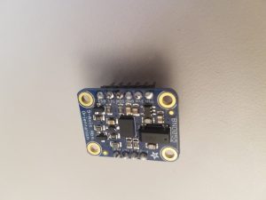
so that it would be easier to insert and extract them into and out of the breadboards, as simply tying wires wasn’t the most reliable way.
But then,
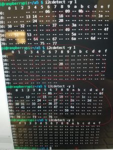
the above happened. Normal operation would mean that we detect only one connected I2C device at address 0x28, and that happened for one IMU. For the other one, however, the addresses seemed to change randomly every time.
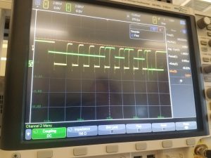
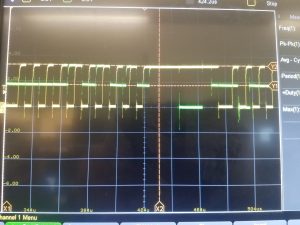
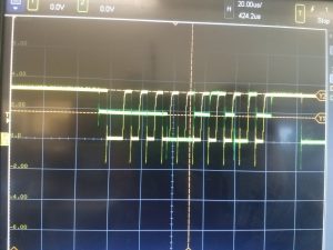
Following Jens’s advice I hooked up an oscilloscope. In the below image, the yellow signal is the clock (SCL) while the green signal is data (SDA) over the I2C protocol. Lo and behold, we have three-level logic: 3.3 V (the input power from the Raspberry Pi 3B+), ground, and 1.7 V. Dr. Kelly mentioned that it is possible that the 3.3V and ground were driving the data line at the same time.
I thought it was a defective product, so I bought another.
OK, 66% failure rate so far, so we returned the two defective items and got two more.
OK, that should not be happening. An 80% failure rate?
At this point the question became “how is one working?” rather than “how are the other four not working?” My conclusion is “i don’t know.” While getting more IMUs is an option, given that I soldered all five and only one turned out to work it may be an exercise in futility. The emergency plan going forward (unless I get another IMU to work) is to have a dummy staff controlled by an artificial “intelligence” going against a staff wielded by an actual human being. The dummy staff will not have an IMU, but rather receive artificial signals from an AI. The real staff will have the sole functioning IMU (whose magnetometer is still finicky about calibrating) and all the normal bells and whistles.
Team Status report 11/17
We’ve gotten behind schedule due to several key factors that we did not anticipate. We only have 1 out of 5 IMU chips that work, and we can’t exactly keep buying them because they’re about 33 bucks a pop. We’re working on a plan to have a regular staff with the working IMU that plays against a dummy AI staff. This way we can show proof of concept of our initial design, but we won’t be able to have an actual multiplayer game like we previously wanted. We’ve talked with our Jens and Professor Kelly about this possible alternative solution, and they seem receptive after watching us struggle to debug the IMU this past week. Also now that we have enough Raspberry Pi’s to successfully develop our communications systems in parallel with developing the IMU and the game progress code, we should be able to accelerate our timeline.
With just a little over 2 weeks left before our in-class demos, we want to create the full staff construction by the end of this week. This way we will only have to finish building the circuit and finishing off the final touches of the code.
Eric Mendez Status report 11/17
This week I worked mainly on getting the staff construction together. With Thanksgiving break coming up, we don’t want to get caught without the able resources to fabricate our end product. I created the 3D CAD design in TinkerCAD of the staff topper and Raspberry Pi Chassis. I got the prints started, and I’m waiting until Monday to pick up the prints from the IDEATE lab. The staff itself is here as well so I will be woodworking it either today or tmr depending on when my friend, who is a shop monitor, is on duty. We are going to shave the top of the staff down to a square shape so the topper of the pi can be attached firmly on top. I made the design with this goal in mind.
Eric Mendez Satus Report 11/10
This week I got the sound to finally output correctly when called as a background thread. Also, we had our midpoint demo on Monday where I showcased our game processing logic. I’ve got almost all the i/o pipelines figured out in terms of the basic game. I programmed it so it would be easy to add more game logic on top of the pre-existing code. I was able to return our previously ordered LED strip because they would have needed a 12v power source, which seemed a bit much for a project like ours. I got some old strips I had from a previous Arduino project. These LEDs are going to be used to signal spell cooldowns as well as current spells being stacked and ready for attack. This week we plan to nail down the physical construction of the staff as well.
Dan Saad Status Report November 9
This week I have been working more on how to work the NRF radio chips & SPI protocols, but have also pivoted to some other ongoing tasks. The search for a displacement display is ongoing, but i reached a decision on the knock sensing (we are now using a simple accelerometer to detect a sudden vertical deceleration rather than ordering a whole new sensor whose sensitivity we can’t set). I have finalized the artwork for the game, and have been looking over the particular values / parameters of spells to ensure that they are in line, but further testing will have to wait until our first physical prototype is built.
Much of my time this week has been dedicated to learning blender / CAD software in preparation for physical construction. I am currently editing a file that we hope to 3D print to form the head of our staff. I have several size specifications at the ready, and should be able to resize, edit, and print the staff head soon. My predicted obstacle here is working out hinges and clasps that would allow us to access the RPi, battery, and other systems easily.
Team A5 Status Report November 9
This past week, we had a preliminary demo for our project. During the demo, we were able to successfully show that our device receiving data and “sending out” data like attack spells thanks to Eric, who has also shown we can start a multithreaded approach to the project to handle synchronization issues. Dan has pretty much completed the artwork for the game as well as the numbers for attack, defense, and healing, although exact balancing is a continuously evolving issue. He has been working on finding a solution to integrate the NRFL01 communications chip, as well as picking up CAD software for printing the staff head, and Donghun has been working on resolving the issue with the IMU module. Possibly due to soldering, one of the IMUs has been damaged beyond repair and the other’s magnetometer won’t calibrate, forcing us to order a replacement. As always, see the individual posts for more details.
We have received a new IMU unit and two battery packs for the raspberry pis, and tomorrow we are meeting to work on deciding how to fabricate everything. We have already put in purchase requests for parts like dowels, so hopefully when we finalize things tomorrow it will be smooth sailing from now on.
Dong Hun Kim November 9 Status Report
This past week, we had our preliminary demo. While the directional part of the IMU module was working properly, last weekend we discovered that the other IMU was not working, so our idea of having two IMUs ready to demo did not work out. The other IMU had problems with the magnetometer, leading to a “garbage in garbage out” situation with the motion classification as well as issues with IMU accuracy due to the accelerometer. Maybe my soldering skills were rusty, so I ordered a new IMU unit to test without soldering to see if that was the issue. In my defense, I shall invoke the time-honored tradition of blaming the equipment. Most of the soldering irons in the lab were complete garbage and could only melt solder at certain angles after a certain amount of time instead of melting the solder instantly. Anyways, tomorrow we’ll go into some basic fabrication so we’ll see how that goes.