
When the project initially started, we purchased two BNO055 IMUs from Adafruit. I soldered the first two
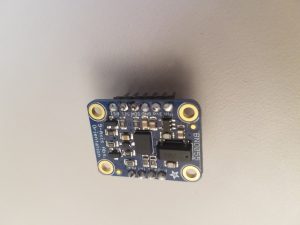
so that it would be easier to insert and extract them into and out of the breadboards, as simply tying wires wasn’t the most reliable way.
But then,
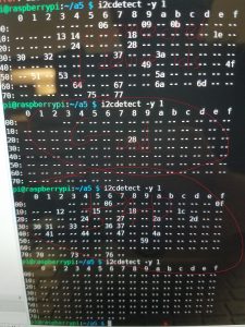
the above happened. Normal operation would mean that we detect only one connected I2C device at address 0x28, and that happened for one IMU. For the other one, however, the addresses seemed to change randomly every time.
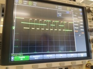
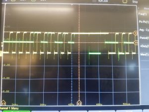
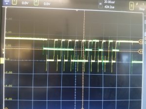
Following Jens’s advice I hooked up an oscilloscope. In the below image, the yellow signal is the clock (SCL) while the green signal is data (SDA) over the I2C protocol. Lo and behold, we have three-level logic: 3.3 V (the input power from the Raspberry Pi 3B+), ground, and 1.7 V. Dr. Kelly mentioned that it is possible that the 3.3V and ground were driving the data line at the same time.
I thought it was a defective product, so I bought another.
OK, 66% failure rate so far, so we returned the two defective items and got two more.
OK, that should not be happening. An 80% failure rate?
At this point the question became “how is one working?” rather than “how are the other four not working?” My conclusion is “i don’t know.” While getting more IMUs is an option, given that I soldered all five and only one turned out to work it may be an exercise in futility. The emergency plan going forward (unless I get another IMU to work) is to have a dummy staff controlled by an artificial “intelligence” going against a staff wielded by an actual human being. The dummy staff will not have an IMU, but rather receive artificial signals from an AI. The real staff will have the sole functioning IMU (whose magnetometer is still finicky about calibrating) and all the normal bells and whistles.